

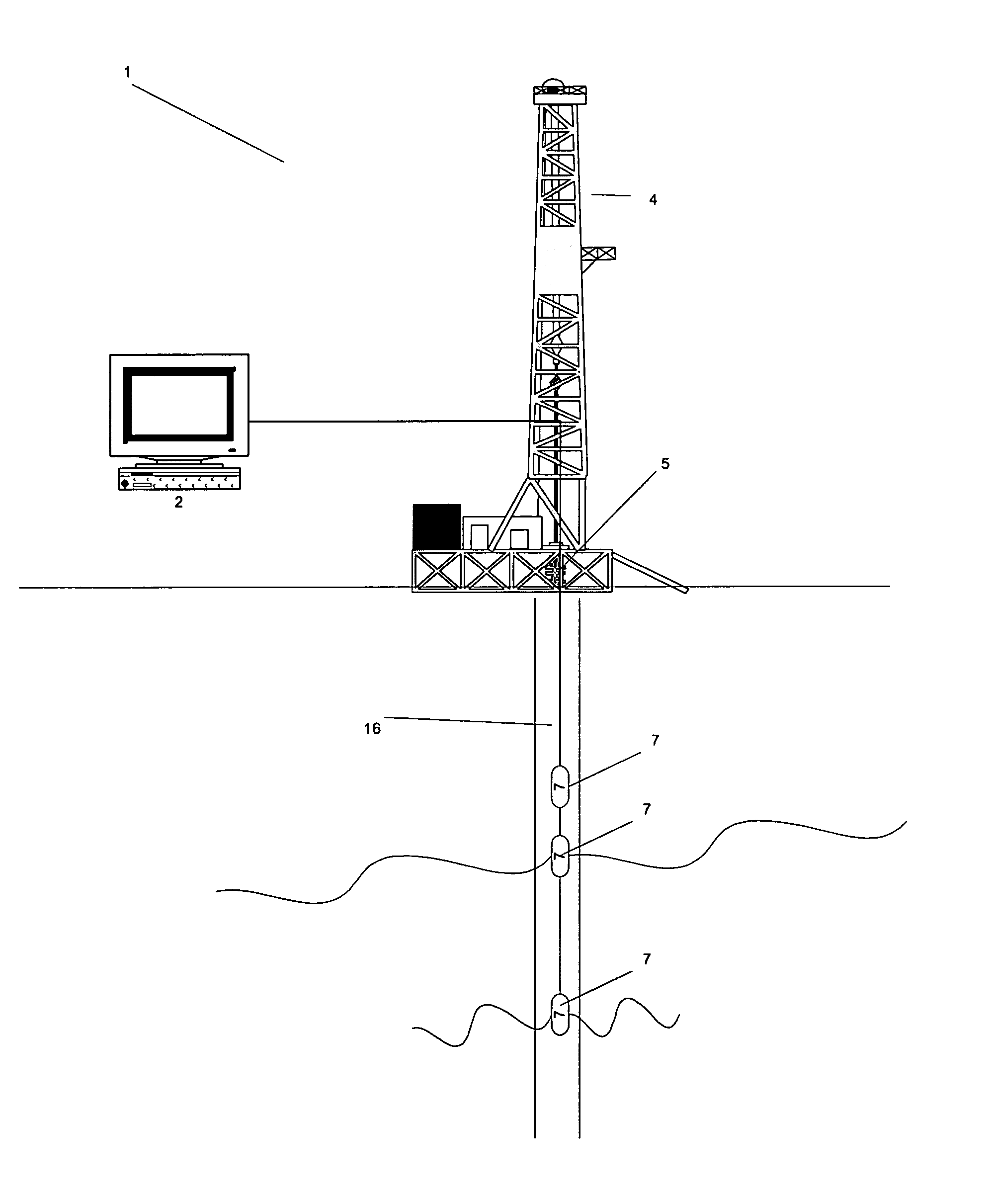
Intelligent system for use in subterranean drilling applications
a technology for intelligent systems and drilling applications, applied in seismicity, geological measurements, surveys, etc., can solve the problems of increasing the cost of using a model such as this, reducing and reducing the efficiency of drilling operations, so as to reduce the overall cost of drilling operations , the effect of reducing the cost of drilling operations
- Summary
- Abstract
- Description
- Claims
- Application Information
AI Technical Summary
Benefits of technology
Problems solved by technology
Method used
Image

Examples
Embodiment Construction
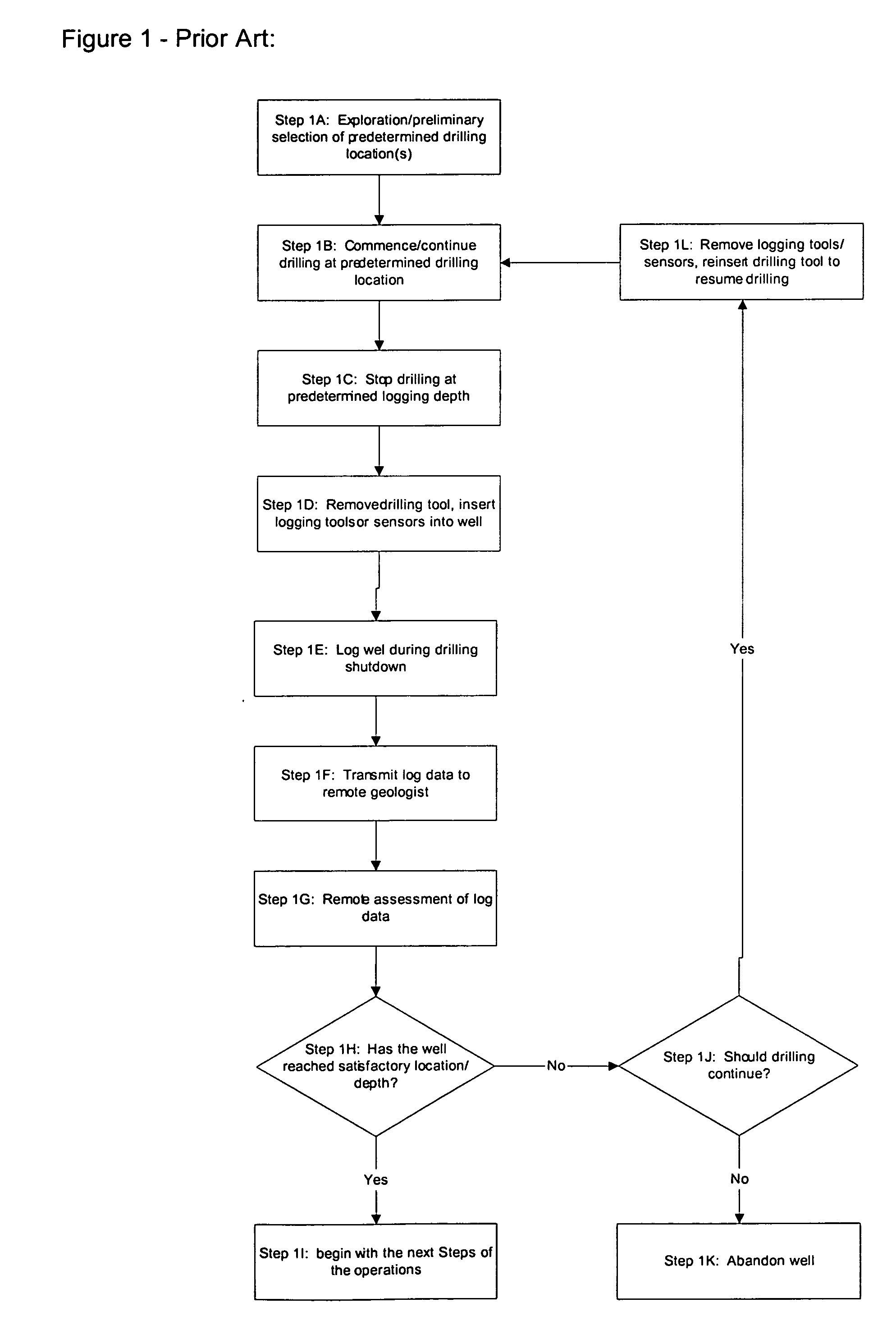
[0054] Prior Art:
[0055] Current methods of assessing and determining the proper drilling depth or tool locations in oil and gas drilling applications are resource-intensive. With a view to demonstrating the shortcomings of the conventional method, as well as framing the backdrop against which the present invention can be discussed, the following is a brief discussion of the general steps involved in present day oil drilling operations.
[0056]FIG. 1 is a process flow diagram of the prior art method of logging and analyzing sensory data for oil and gas drilling applications. The first step which is shown in the Figure at 1A is the exploration step. In the exploration step, a company, by various prior art means including seismic assessment or the like, will determine the spot or spots at which oil wells should be attempted to be drilled. These are referred to herein as predetermined drilling sites.
[0057] Shown at Step 1B in FIG. 1 is the actual commencement of drilling at one such pr...
PUM
 Abstract
Description
Claims
Application Information