Form changing device, object action encoding device, and object action decoding device

Active Publication Date: 2006-12-21
NEC CORP
View PDF4 Cites 27 Cited by
  • Summary
  • Abstract
  • Description
  • Claims
  • Application Information

AI Technical Summary

Benefits of technology

[0012] Thus, it is an object of the invention to eliminate the calculation amount

Problems solved by technology

However, this method suffers from a proble

Method used


Image

  • Form changing device, object action encoding device, and object action decoding device
  • Form changing device, object action encoding device, and object action decoding device
  • Form changing device, object action encoding device, and object action decoding device

Examples


first embodiment

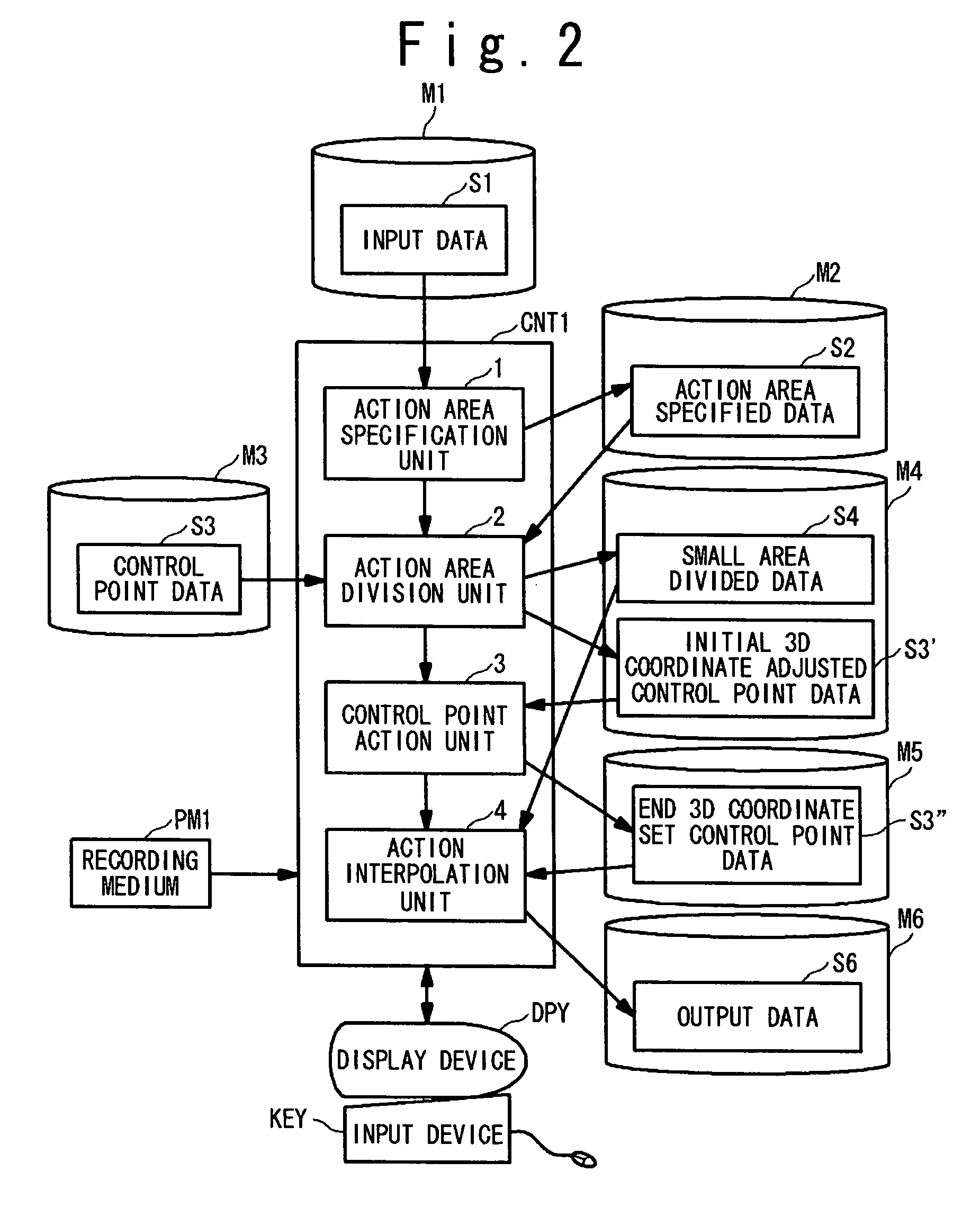
[0080]FIG. 2 is a block diagram showing the configuration of the shape deforming device of the present invention. The shape deforming device deforms a human expressionless face image into an expressive action face image. The shape deforming device of this embodiment is composed of: a processor CNT 1, storage devices M1 to M6, a display device DPY, and an input device KEY. A plurality of storage devices M1 to M6 are each composed of, for example, a magnetic disc. Of these devices, the storage device M1 stores the input data S1 concerning the human expressionless face. The storage device M6 stores the output data S6 concerning the human expressive action face. The other storage devices M2 to M5 store the control data or the interim results required in the course of processing. The display device DPY is, for example, a liquid crystal display, and is used for displaying an expressive action face image obtained as the output data S6 or for displaying data in the course of processing. The...

second embodiment

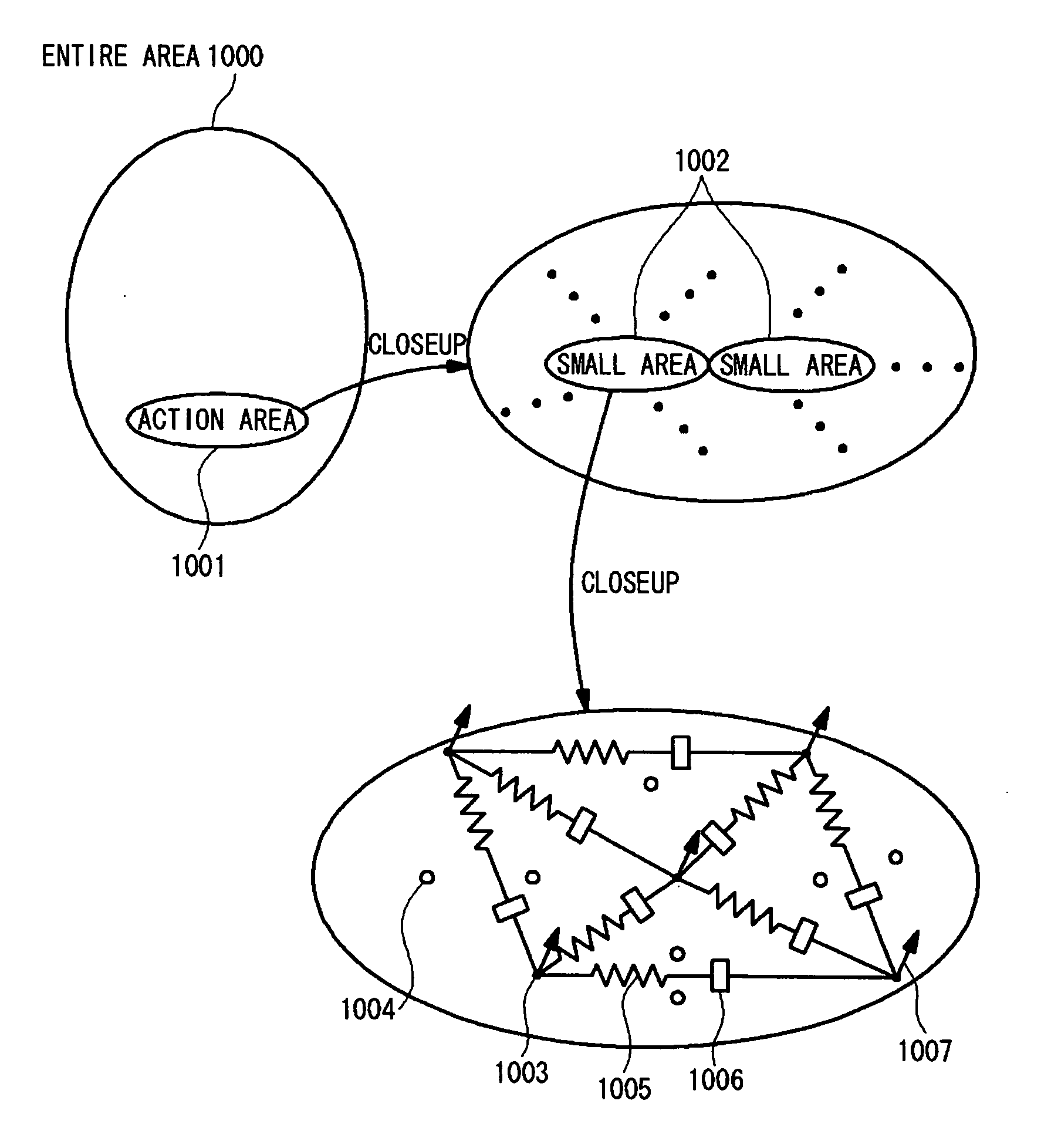
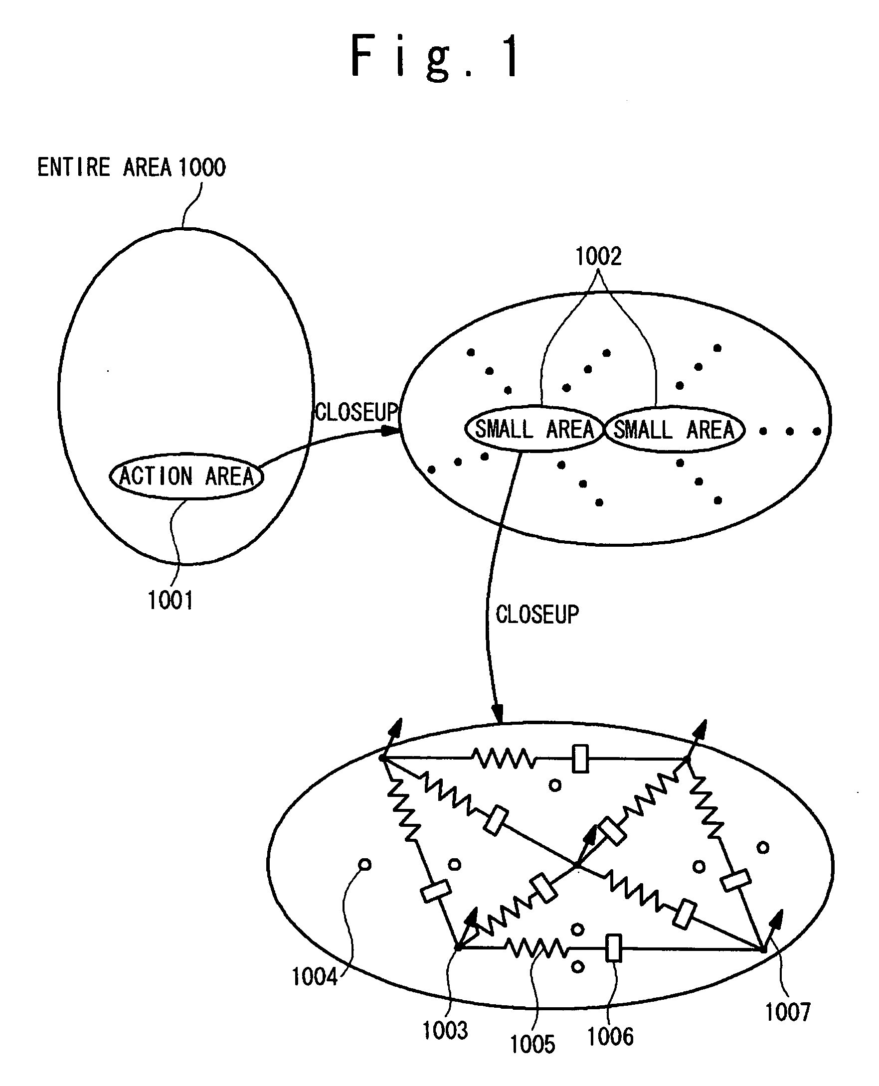
[0098] In the second embodiment, the action area is divided into a plurality of small areas, and the movement amount is calculated independently in units of small areas. Therefore, when there is a distinct difference in the movement amount between adjacent small areas, a discontinuous section such as a step difference or the like is formed at a boundary portion between these small areas. For example, as shown in FIG. 10A, when there arises a difference in the movement amount between two small areas 1001 and 1002 that are connected together before their movements, they may be separated from each other as shown in FIG. 10B, or they may be partially superimposed on each other as shown in FIG. 10C. The adjacent small areas adjustment unit 5 of this embodiment has a function of adjusting discontinuous condition occurring at the boundary portion between such small areas. As is the case with the other function units 1 to 4, the adjacent small areas adjustment unit 5 can be achieved by a pr...

fourth embodiment

[0115]FIG. 18 is a block diagram of the facial action encoding device according to the present invention, which calculates and outputs the action area and the external force at expressive action from the face three-dimensional data of a certain person at non-expression and at expressive action. The facial action encoding device of this embodiment includes a processor CNT11, storage devices M11 to M15, a display device DPY, and an input device KEY. A plurality of storage devices M11 to M15 are each composed of, for example, the magnetic disc. Of these devices, the storage device M11 stores the expressionless face 3D data S110 and expressive action face 3D data S101 as input data, the storage device M15 stores the external force data S12 of the expressive action and an action area S13 of the expressive action as output data, and the other storage devices M12 to M14 store the interim results or a control data required in the course of processing. The display device DPY is composed of, ...


PUM


Abstract

A shape deformation encoding device includes: a calculation unit for calculating a difference data between a pre-deformation shape data which represents a shape of an object before shape change and a post-deformation shape data which represents a shape of the object after shape change; and a determination unit for determining an action area on which the shape change of the object is arisen and an external force which is acted to the action area for the shape change, based on the pre-deformation shape data and the difference data. The action area includes a plurality of small areas, each of the plurality of small areas includes a plurality of control points, and the external force is calculated as an external force required to deform the plurality of small areas from before to after the shape change independently based on the physical model structure of each of the plurality of small areas. The physical model structure in which the plurality of control points are connected together with springs and dampers are used as a physical model structure.

Description

TECHNICAL FIELD [0001] The present invention relates to a shape deforming device, object action (shape change) encoding device and object action (shape change) decoding device for deforming an object. Especially, the present invention relates to a shape deforming device, object action (shape change) encoding device and object action (shape change) decoding device for providing an expression to a face by deforming a shape of a part of the face. BACKGROUND ART [0002] In recent years, in the fields of VR (virtual reality) and CG (computer graphics), technologies for deforming a face image has been used for the purpose of providing an expression. For example, by detecting a change in a facial expression of a certain person and then applying the same change to a face image of the same person or a different person, a personified agent is provided which changes an expression in synchronization with a particular person. [0003] There are mainly two trends in such a facial expression synthesi...

Claims


Application Information

Patent Timeline
IPC IPC(8): G06K9/36G06T13/20
CPCG06T9/001G06T13/20G06T13/40G06T17/00
Inventor MARUGAME, ATSUSHI
Owner NEC CORP
Why Eureka
Try Eureka