
Support system for transition ducts

a support system and transition duct technology, applied in the direction of efficient propulsion technologies, machines/engines, light and heating apparatus, etc., can solve the problems of complicated sealing, difficult to predict, and require more expensive manufacturing and repair techniques, so as to prevent the leakage of neighboring duct bodies at least partially, the effect of minimizing leakag

Active Publication Date: 2006-12-28
SIEMENS ENERGY INC
View PDF31 Cites 76 Cited by
  • Summary
  • Abstract
  • Description
  • Claims
  • Application Information

AI Technical Summary

Benefits of technology

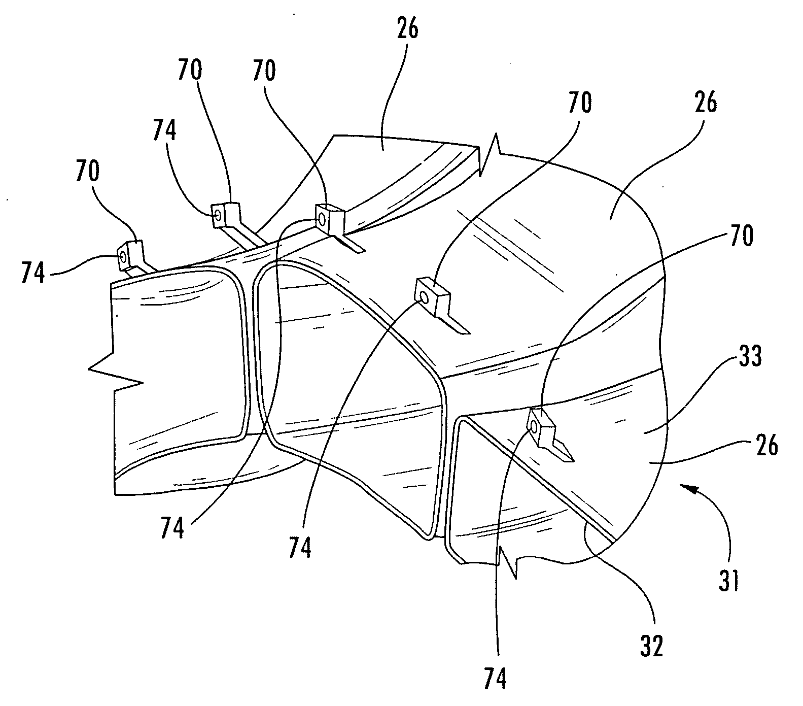
[0016] Neighboring support ring segments define an interface. The interface occurs along an imaginary path across the outlet of the common transition duct body. As a result, leakage between adjacent transition duct bodies can be at least partially prevented.
[0021] The system further includes a support ring formed by a plurality of circumferentially arrayed support ring segments. Each support ring segment has an outer span and an inner span joined by a central column such that lateral openings are defined on each side of the central column. Two braces extend from the outer span of each support ring segment. The lateral openings of neighboring support ring segments form a common opening. One or more seals, such as rope seals or spring leaf seals, are provided along the common opening. A flexible seal is operatively connected to each of the outer and inner span of at least one of the support ring segments. Thus, the flexible seal can at least partially minimize leakage between the support ring segment and the outlet.
[0022] A portion of the transition duct body is inserted into one of the common openings such that two substantially adjacent ring segments substantially matingly surround the duct body. The interface of neighboring support ring segments occurs along an imaginary path across the outlet of the common transition duct body. Thus, leakage between neighboring duct bodies can be at least partially prevented.

Problems solved by technology

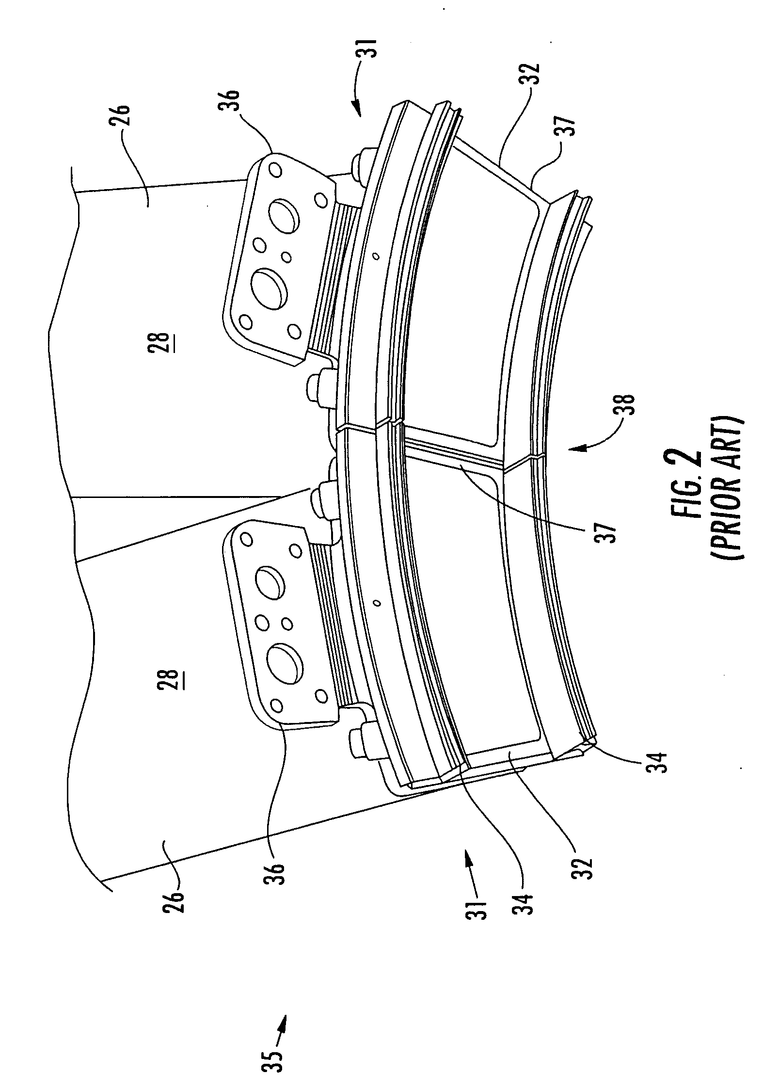
Leakages at these interfaces are difficult to predict due to large tolerances and large transient deflections; thus, complicated sealing issues are introduced into the design of the support system 35.
The known system 35 also includes relatively complex and wear prone subcomponents, requiring more expensive manufacturing and repair techniques and raising concerns of system downtime.
Moreover, the known support system 35 suffers from large thermal stresses at support attachment locations, uses expensive components, and involves difficult and labor intensive assembly.

Method used


Image

  • Support system for transition ducts
  • Support system for transition ducts
  • Support system for transition ducts

Examples


Embodiment Construction

[0032] Embodiments of the invention are directed to a transition duct support system. Aspects of the invention will be explained in connection with a system for supporting the exit end of a transition duct, but the detailed description is intended only as exemplary. Embodiments of the invention are shown in FIGS. 3-8, but the present invention is not limited to the illustrated structure or application.

[0033] A transition exit support system according to aspects of the invention includes a plurality of exit support ring segments. FIG. 3 shows an individual exit support ring segment 52. Each support ring segment 52 can have an outer span 54 and an inner span 56. In one embodiment, the outer and inner spans 54, 56 can be generally arcuate. The arcuate outer and inner spans 54, 56 can be substantially concentric. The spans 54, 56 can be joined by a central column 58 to define a lateral opening 60 on each side of the central column 58. The spans 54, 56 and the central column 56 can be m...


PUM


Abstract

Aspects of the invention relate to a system for supporting the exit end of a transition duct. The system includes a plurality of support ring segments that collectively form an annular support ring assembly. Each support ring segment can have an outer span and an inner span that are joined by a central column. Lateral openings can be defined on each side of the central column. The lateral openings of two adjacent support ring segments can cooperate to form an opening. An outlet region of a transition duct can be inserted into a respective opening and engage seals provided along the opening. The interface of adjacent ring segments occurs along an imaginary line across the outlet of the common transition duct body. Each support ring segment can be attached to the transition duct as well as to a fixed portion of the engine such as the turbine stationary support structure.

Description

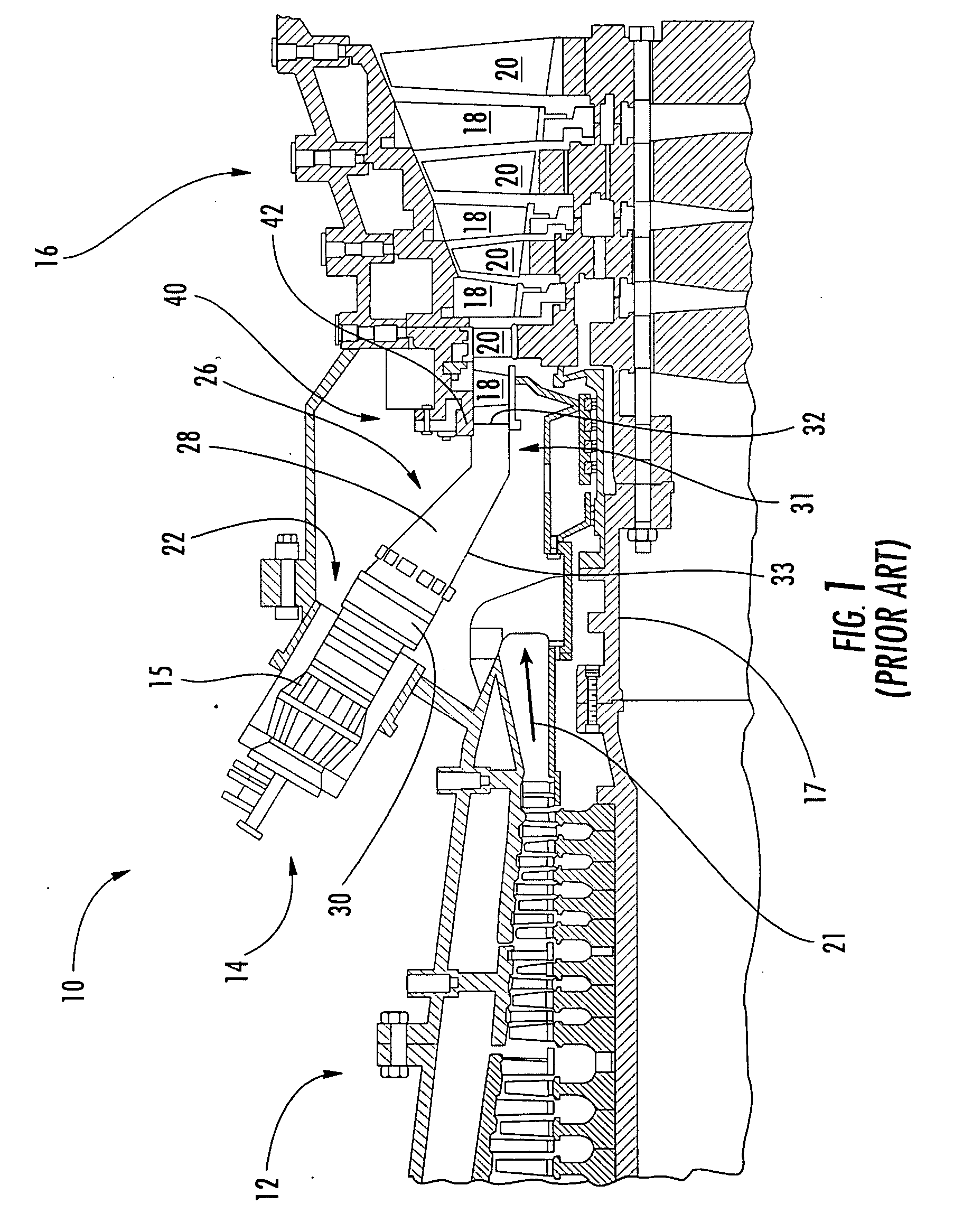
CROSS-REFERENCE TO RELATED APPLICATIONS [0001] This application is a Continuation-In-Part of U.S. application Ser. No. 11 / 167,464 filed Jun. 27, 2005.FIELD OF THE INVENTION [0002] The invention relates in general to turbine engines and, more particularly, to transition ducts in the combustor section of a turbine engine. BACKGROUND OF THE INVENTION [0003]FIG. 1 shows an example of a combustion turbine engine 10. The turbine engine 10 includes a compressor section 12, a combustor section 14, and a turbine section 16. The combustor section 14 can include a plurality of combustors 15 (only one of which is shown) arranged in an annular array around a rotor 17. The turbine section 16 includes alternating rows of stationary airfoils 18 and rotating airfoils 20. [0004] In operation, air is drawn in through the compressor section 12, where it is compressed and driven towards the combustor section 14. The compressed air 21 can be directed to the combustor 15 through an air intake 22. The air ...

Claims


Application Information

Patent Timeline
Patent Type & Authority Applications(United States)
IPC IPC(8): F02C7/20
CPCF01D9/023F02C7/20F23R3/425F23R3/60F05D2300/603F05D2250/25F05D2250/31F05D2250/322Y02T50/675Y02T50/60F02C7/00F01D5/12F01D25/00
Inventor WEAVER, ADAMWILSON, JODY
Owner SIEMENS ENERGY INC
Learn More