Method and apparatus suitable for measuring the displacement or load on an aircraft component

a technology for aircraft components and displacement, applied in the field of aircraft, can solve problems such as component bending, and achieve the effect of reducing one or more disadvantages

Inactive Publication Date: 2006-12-28
AIRBUS UK
View PDF18 Cites 15 Cited by
  • Summary
  • Abstract
  • Description
  • Claims
  • Application Information

AI Technical Summary

Benefits of technology

[0005] It is an object of the present invention to provide a load measuring apparatus suitable for external use on an aircraft and which mitigates one or more of the disadvantages outlined above. Alternatively, or

Problems solved by technology

The loads sustained by the aircraft component can cause the component to bend a

Method used


Image

  • Method and apparatus suitable for measuring the displacement or load on an aircraft component
  • Method and apparatus suitable for measuring the displacement or load on an aircraft component
  • Method and apparatus suitable for measuring the displacement or load on an aircraft component

Examples


second embodiment

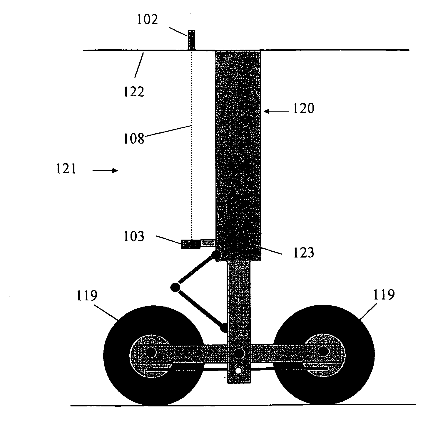
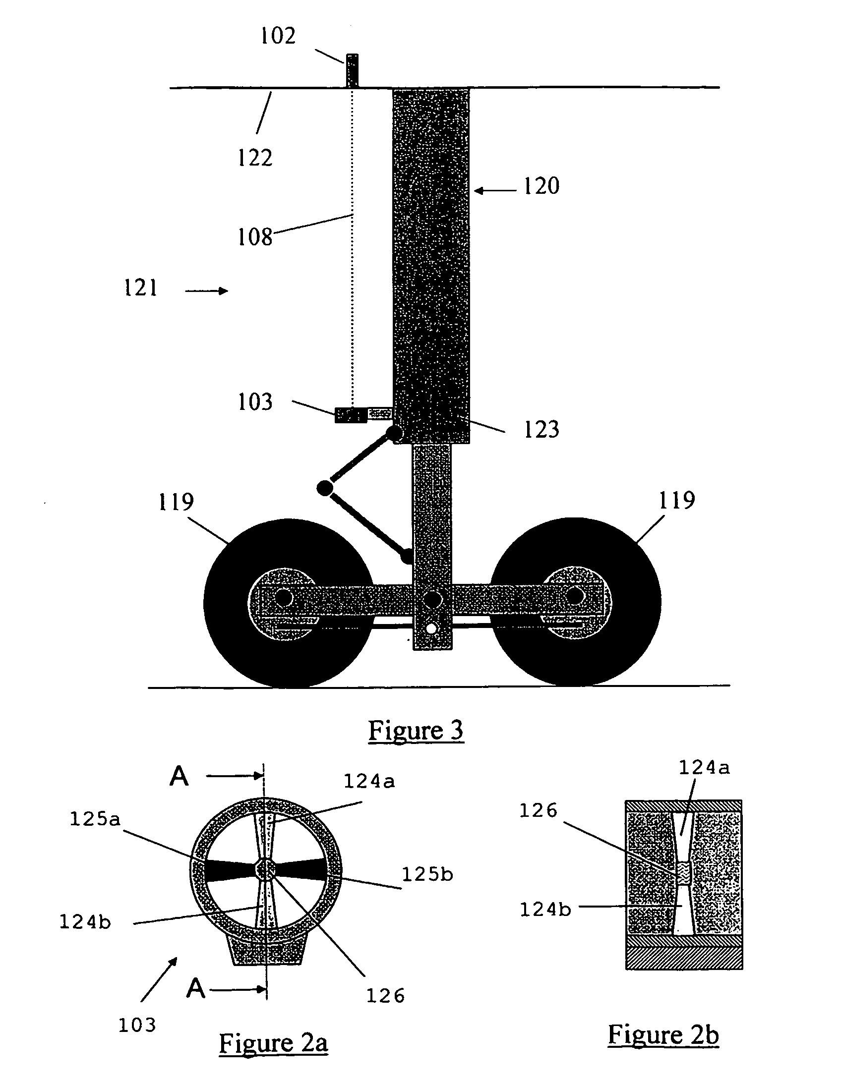
[0065]FIGS. 2a to 2e illustrate a detector 103 of load measuring system for measuring loads according to the invention. The microwave detector 103 is arranged such that the system is able to detect movement in two dimensions. The detector 103 is shown in plan view in FIG. 2a. A cross-section taken along the plane A-A is shown in FIG. 2b. The detector 103 comprises two pairs of antennae 124a,b and 125a,b. The antennae of each pair are positioned opposite each other and have microwave detection surfaces that are positioned so that the beam of radiation 108 from the emitter (not shown) is generally transverse to the detection surfaces. The antennae 124, 125 are all joined by means of a stabiliser 126 that connects the tips of the antennae 124, 125 and reduces unwanted vibration of the antennae at the tips. The antennae form a cruciform arrangement, one pair 124a, 124b detecting relative movement along a first axis (for example, an x-axis, which is vertical in FIGS. 2a to 2e) the other ...

fifth embodiment

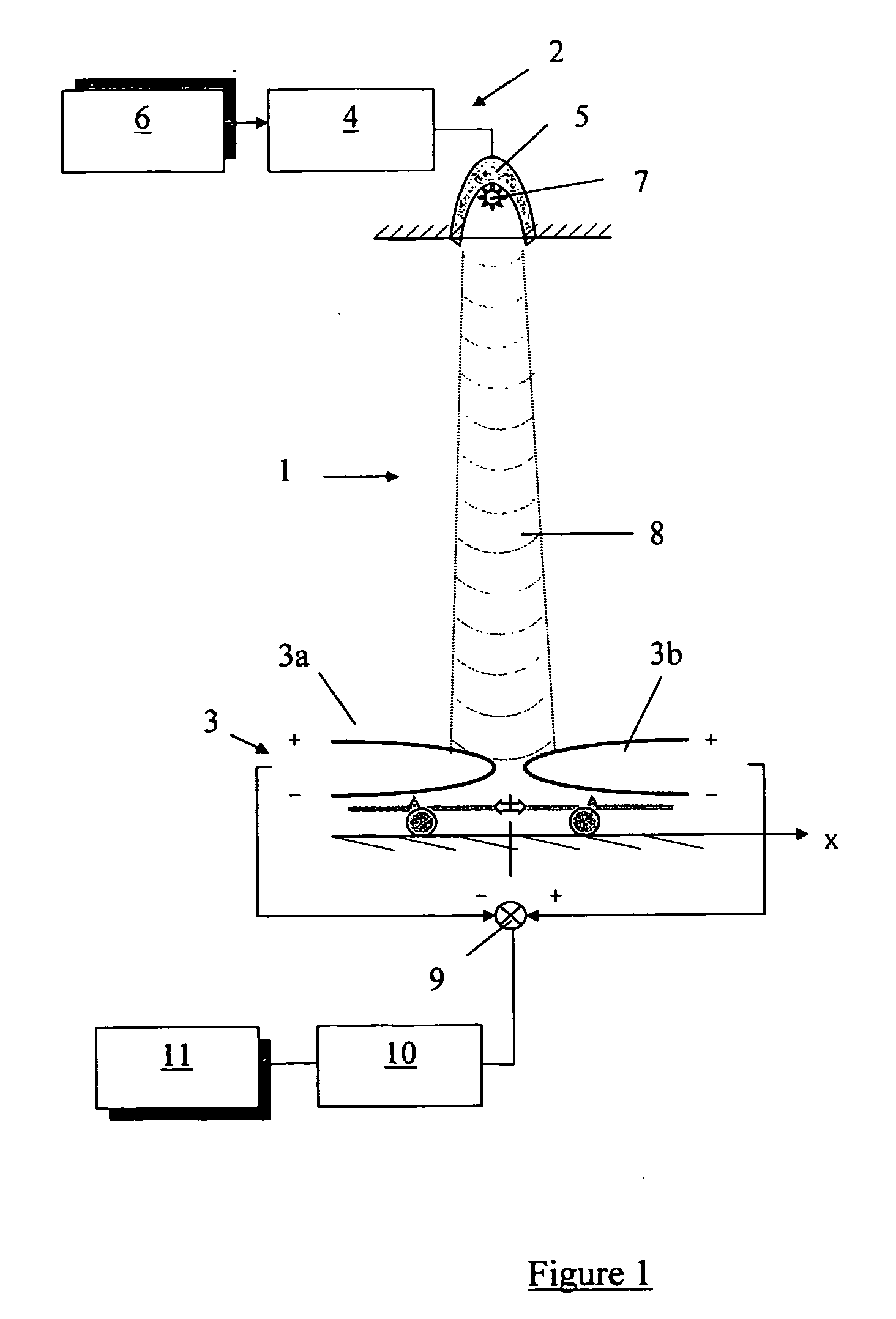
[0070]FIG. 5 shows an aircraft 400 landing on a runway in accordance with the invention. The loads on the landing gear 421 of the aircraft 400 are monitored during landing by means of apparatus according to the embodiment described with reference to FIG. 3. After touchdown the brakes are applied and the loads on the landing gear 421 and on the braking system become significant. The braking of the aircraft 400 is controlled by a control system (not shown) that controls the braking in such a way as to reduce the likelihood of the loads on the landing gear 421 that are monitored becoming greater than preset thresholds. The use of microwave antennae in a system for load measuring as described above in relation to the drawings has many potential advantages over the known use of strain gauges. The microwave antennae are not bonded directly to the structure, and may therefore readily dismountable. The feature of the microwave measurement system being a wireless system also has significant ...


PUM


Abstract

The load on an aircraft component, such as the load on a landing gear leg during braking, is measured with a contactless, all-weather displacement measuring system. The system includes a control unit a controllable microwave emitter of electromagnetic radiation and a microwave detector comprising a plurality of antennae. When the aircraft component is subjected to a load relative movement of the emitter and detector is caused. The detector generates in response to microwave radiation received from the focused beam of radiation emitted by the emitter a signal that is received by a signal processor of the control unit. The signal received by the control unit depends on the relative positions of the emitter and detector. The control unit is arranged to provide an output signal representative of the load sustained by the aircraft component. The system may be used to control braking in dependence on the output signal so as to maximise braking efficiency without overloading the landing gear leg.

Description

BACKGROUND OF THE INVENTION [0001] The present invention relates to an aircraft including an apparatus for measuring the load sustained by an aircraft component and to a method of measuring such a load. In particular, the present invention relates to an apparatus for determining the load sustained by an aircraft when braking and / or manoeuvring the aircraft on the ground. [0002] When an aircraft manoeuvres on the ground (including, for example, immediately after touch down), the aircraft is subjected to various loads including vertical wheel to ground loads and horizontal drag loads including, for example, loads caused by friction between the tyres of the wheels of the aircraft and the ground. The landing gear is subjected to significant horizontal loads on braking. The landing gear and other components of the aircraft have to be carefully designed in order for the aircraft to be able to withstand such loads, and other operational loads, but without unduly increasing the mass of the ...

Claims


Application Information

Patent Timeline
IPC IPC(8): G01L1/24B64C25/00B64C25/44B64C25/46B64C25/58G01L1/25G01L5/00
CPCB64C25/001B64C25/445G01L5/00B64C25/58G01L1/25B64C25/46
Inventor GIAZOTTO, ALESSANDRO RICCARDO BRITANNICO
Owner AIRBUS UK
Why Eureka
Try Eureka