Weighing module with precisely-positionable overload protection device

a protection device and weighing module technology, applied in the field of weighing modules, can solve the problems receiving device exposed, damage to the sensitive weighing cell mechanism, etc., and achieve the effect of affecting the weighing resul

Active Publication Date: 2006-12-28
METTLER TOLEDO GMBH
View PDF17 Cites 10 Cited by
  • Summary
  • Abstract
  • Description
  • Claims
  • Application Information

AI Technical Summary

Benefits of technology

[0027] In a particularly preferred embodiment, the positioning device and possible further fastening areas of the weighing module are equipped with means, preferably raised pad surfaces, to distance the housing of the weighing cell, in parti

Problems solved by technology

However, it is also possible for the load receiver to be exposed to transverse forces which in the absence of provisions for uncoupling can be passed on through the force-transmitting linkage to the weighing cell where they can cause damage to the sensitive weighing cell mechanism.
However, the disclosed embodiment of this overload protection device can absorb only those transverse forces that are applied from either side, but not from the front or back.
As a first disadvantage of this configuration, with large transverse forces the force-transmitting linkage due to its guided displacement will bear against the housing-based stop and the transverse forces are transmitted to the weighing cell mechanism as tensile or compressive forces.
In some applications, a second disadvantage of the discl

Method used


Image

  • Weighing module with precisely-positionable overload protection device
  • Weighing module with precisely-positionable overload protection device
  • Weighing module with precisely-positionable overload protection device

Examples


Embodiment Construction

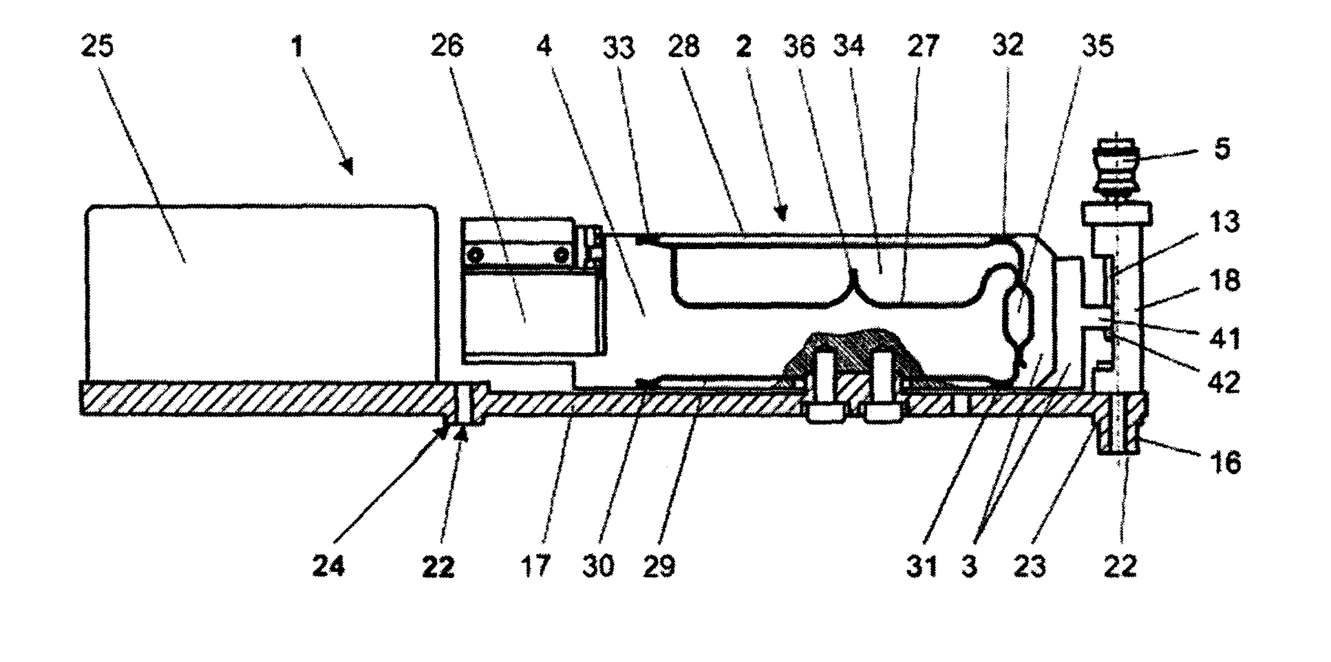
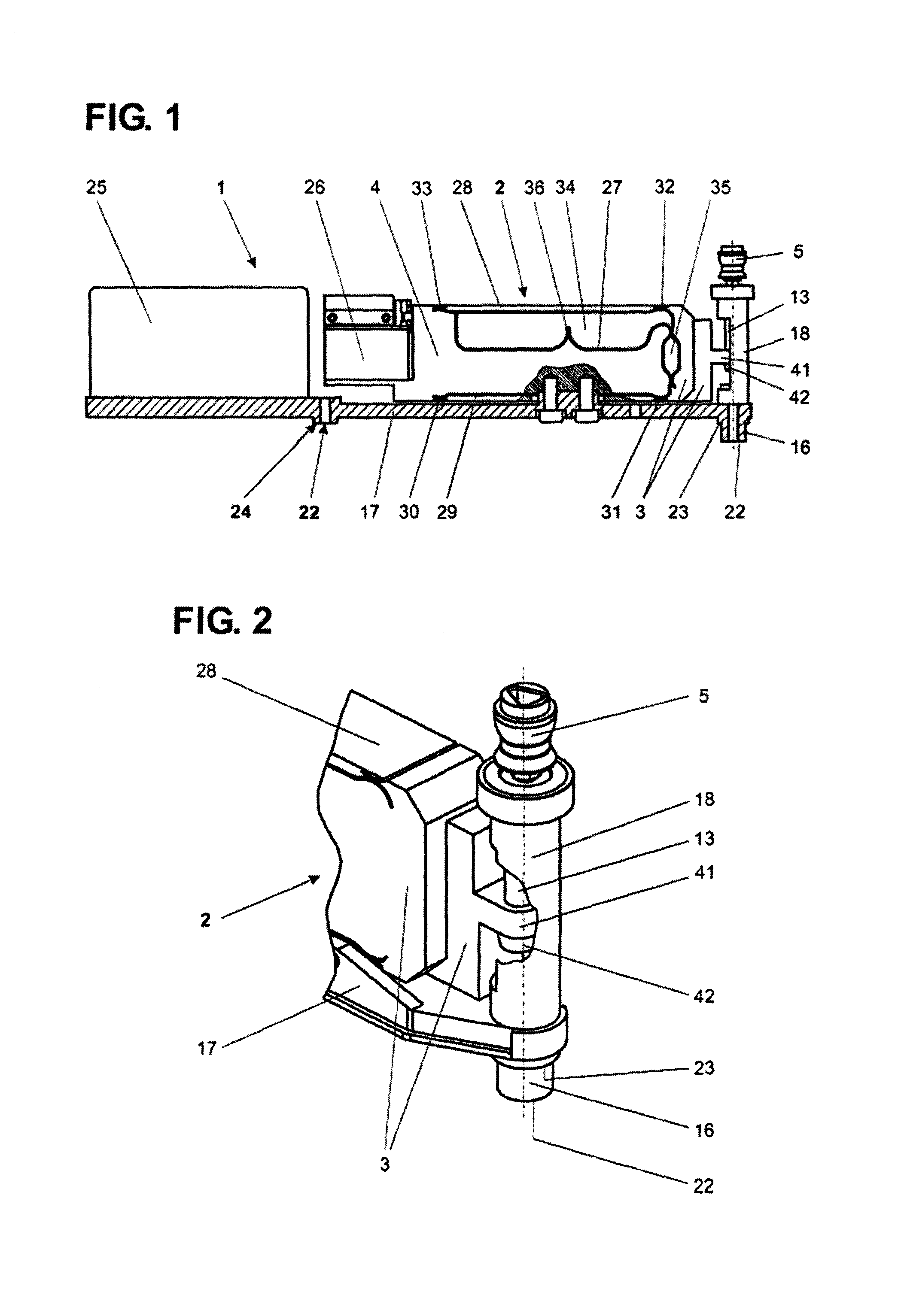
[0040]FIG. 1 illustrates a weighing module 1 from which the housing top has been removed. Installed on a floor part 17 are a weighing cell 2 with its force-compensation device 26, and the signal-processing module 25. The weighing cell 2 includes a force-transmitting mechanism formed out of a monolithic, substantially brick-shaped material block in which distinct material portions are separated from each other by material-free spaces in the form of narrow linear cuts 27 traversing the material block perpendicular to the plane of its largest lateral surfaces. The material portions form a parallelogram with an upper parallelogram guide 28 and a lower parallelogram guide 29, one parallelogram leg forming a stationary portion 4, and a vertically displaceable parallelogram leg forming the load-receiving portion 3. The parallelogram legs 3, 4 and the parallelogram guides 28, 29 are connected to each other through flexible connecting portions 30, 31, 32, 33 which are of a concave shape, del...


PUM


Abstract

A weighing module 1 has a force-transmitting linkage 13 arranged between the load-receiving portion 3 of the weighing cell 2 and the load receiver 5, with an overload protection device that precisely maintains its position being an integral part of the force-transmitting linkage 13. By means of a positioning element 7, 107, 207, the load receiver 5 is positioned without play relative to the load-receiving portion 3 in the plane that extends orthogonal to the load direction, and the load receiver 5 is also guided in the load direction without play. When forces in excess of the pre-tension force of the elastic element 8 act on the load receiver 5, the latter has the capability of being displaced in the load direction and to tip in all directions that are orthogonal to the load direction. The housing part 18 serves to delimit at least the range of linear downward deflection as well the tipping movement of the load receiver 5 when the load receiver 5 is exposed to transverse forces and to overloads. The rotation constraint 20 is rigidly connected to the load receiver 5 and engages a housing-connected recess 21. To position the load receiver 5 relative to its operating environment, a positioning device 16 is provided, whose central longitudinal axis coincides with the central longitudinal axis of the load receiver 5.

Description

TECHNICAL FIELD [0001] The present invention relates to a weighing module that is equipped with a precisely position-maintaining overload protection device arranged between the weighing cell and the load receiver. BACKGROUND OF THE ART [0002] The present invention relates to a weighing module that is equipped with a precisely position-maintaining overload protection device arranged between the weighing cell and the load receiver. [0003] An overload protection device in a balance has the function of uncoupling the load receiver, specifically the weighing pan, from the weighing cell when a maximum permissible load is exceeded, with the force vector of the load acting on the weighing pan in a largely vertical direction. As a result, the weighing cell is protected from the consequences of excessive primarily vertical forces which can be generated either statically by a weight that exceeds a maximum permissible load, or dynamically, for example if a load is set down too rapidly. However,...

Claims


Application Information

Patent Timeline
IPC IPC(8): G01G23/02
CPCG01G23/005
Inventor BURKHARD, HANS-RUDOLFMETZGER, ANDREASSCHILLING, PETER
Owner METTLER TOLEDO GMBH
Why Eureka
Try Eureka