

Laser beam irradiation apparatus and pattern drawing method
a laser beam and pattern technology, applied in the direction of photomechanical equipment, instruments, manufacturing tools, etc., can solve the problems of damage to each transferred part, long processing time for drawing the pattern, and difficulty in aligning the start and end points of each segment of each straight pattern b
- Summary
- Abstract
- Description
- Claims
- Application Information
AI Technical Summary
Problems solved by technology
Method used
Image

Examples
first embodiment
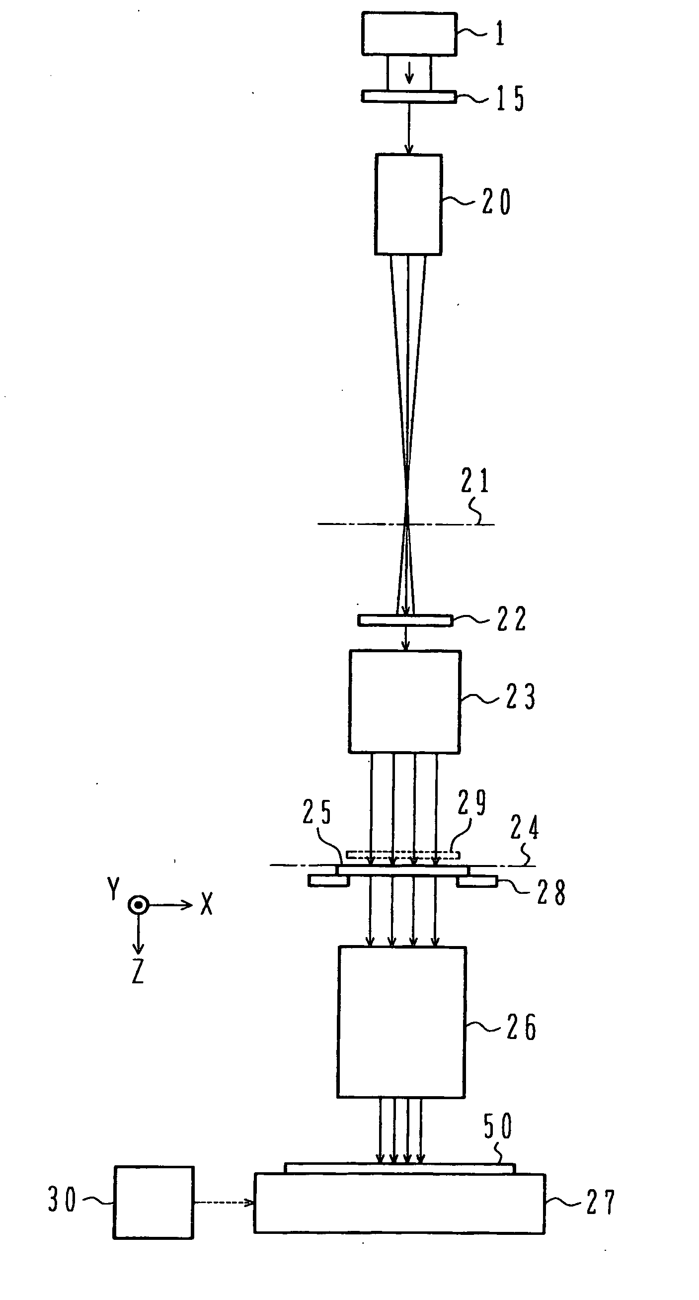
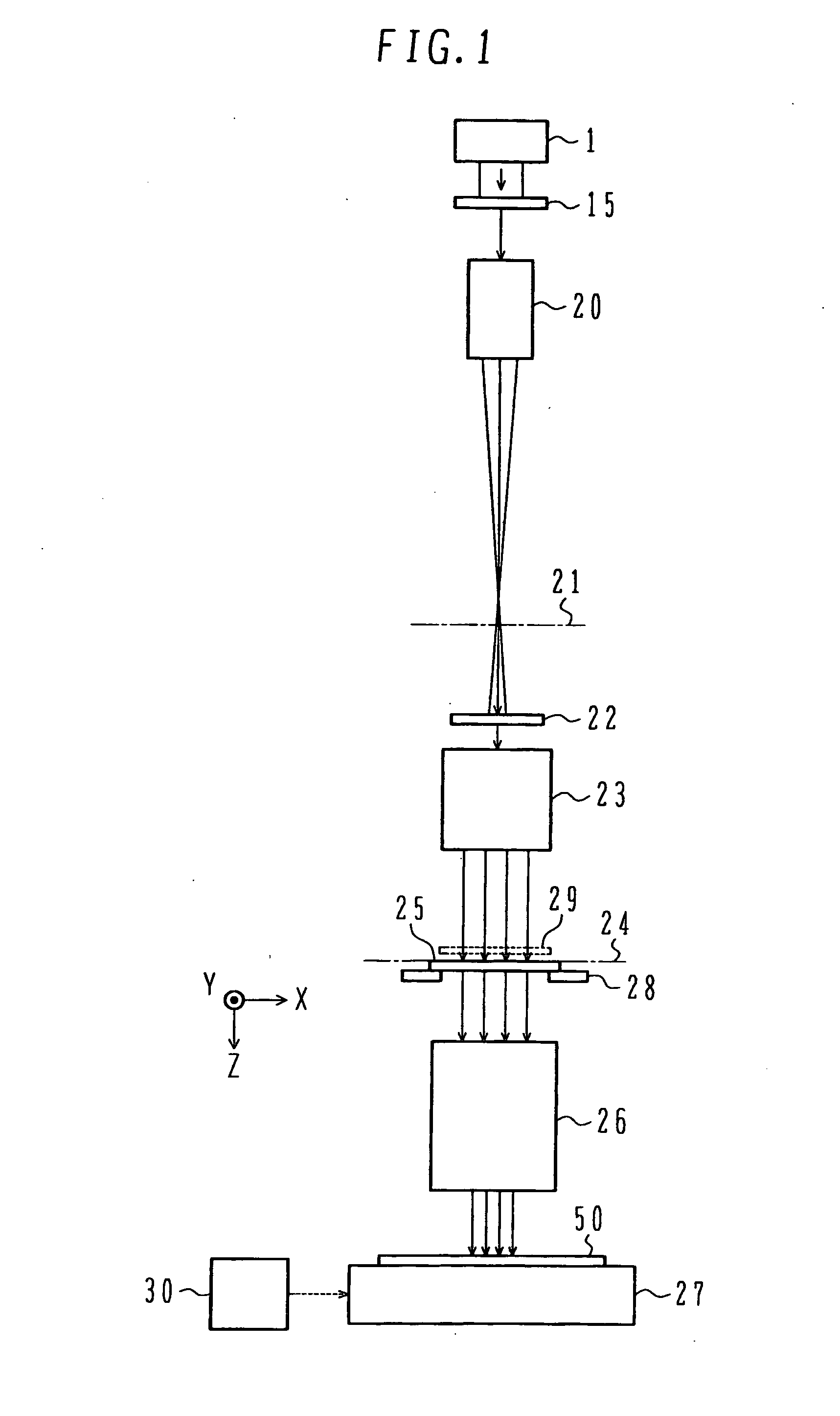
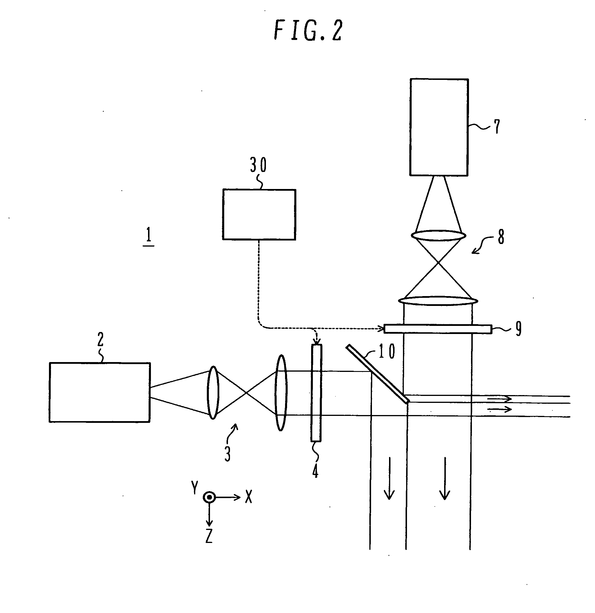
[0040]FIG. 1 shows a schematic diagram of a laser beam irradiation apparatus according to a A laser source 1 emits a laser beam. A first mask 15 shapes the cross section of the laser beam emitted from the laser source 1. The resultant laser beam enters a first-stage zoom lens system 20. The first mask 15 includes, e.g., a laser-beam blocking plate having a through-hole, which shapes the cross section of an incident laser beam. The first-stage zoom lens system 20 provides, on a virtual plane 21, an image of the cross section of the laser beam shaped by the first mask 15, i.e., the through-hole of the first mask 15. The imaging magnification of the lens system 20 is, e.g., 1 / 20 to 1 / 34. The detailed structure of the first mask 15 and the laser source 1 will be described below with reference to FIGS. 2 and 3.
[0041] The laser beam passing across the virtual plane 21 enters a diffractive optical element (DOE) 22. The DOE 22 splits the incident laser beam into a plurality of, e.g., 100 l...
second embodiment
[0079] In the method each irradiation pattern for drawing the line segment 100Y includes a plurality of separate points, thus preventing overlap of irradiation patterns formed in different shots. Although each irradiation pattern includes a plurality of separate points, regions actually joined as a transferred film to a substrate become unbroken one region because of the transmission of heat. The amount of heat input in each part joined by the heat transmission is smaller than that in each part joined by direct laser-beam irradiation.
[0080] In addition, each region joined by the heat transmission is not directly irradiated with a laser beam in the next shot, in which heat is transmitted to the region. Accordingly, probably, each joined region is not damaged by the following laser-beam irradiation.
[0081]FIG. 7 shows one example of the irradiation pattern for drawing of the line segment 100Y. Other irradiation patterns are available. An available irradiation pattern will now be desc...
third embodiment
[0091] When the object 50 is rotated by 90°, the similar patterns can be drawn. However, this approach has the following problem: Generally, as the screen size of a thin-shaped display increases, the size of a substrate therefore increases. In drawing patterns on the substrate, a stage mechanism for rotating the substrate has a tendency to move unevenly, leading to degradation of pattern positioning accuracy. it is unnecessary to rotate the substrate. Advantageously, a stage mechanism need not rotate.
[0092] According to another approach, rotating the DOE 22 shown in FIG. 1 by 90° can achieve drawing of the similar patterns. In rotating a DOE, however, it is difficult to align the rotation center of the DOE to the optical axis of another optical element. Disadvantageously, misalignment of drawn patterns may easily occur due to an error in positioning the DOE. According to the third embodiment, since the DOE is not rotated, misalignment of patterns hardly occurs.
PUM
| Property | Measurement | Unit |
|---|---|---|
| incident angle | aaaaa | aaaaa |
| transmission area | aaaaa | aaaaa |
| transmission | aaaaa | aaaaa |
Abstract
Description
Claims
Application Information