
Friction stirring of high softening temperature materials using new surface features on a tool

a high softening temperature material and friction stirring technology, applied in the direction of manufacturing tools, soldering devices, auxillary welding devices, etc., can solve the problems of tool material, inability to test, and inability to achieve the effect of lstm,

Inactive Publication Date: 2006-12-28
MAZAK CORP
View PDF17 Cites 37 Cited by
  • Summary
  • Abstract
  • Description
  • Claims
  • Application Information

AI Technical Summary

Benefits of technology

[0018] The present invention is a method of selecting a geometry for a friction stirring tool, said tool having a melting point that is higher than the workpiece material, wherein the tool is placed in motion against the workpiece to generate heat in the workpiece such that workpiece material is transported in surfa

Problems solved by technology

However, some of the geometries are not technically feasible because the strength of the tool material is exceeded during solid state processing.
Subsequent publications and patent applications have disclosed variations of these tool geometries, some of which have not been tested and are not feasible for these LSTMs.
To this point in time, millions of dollars have been spent and there has not been a successful model that can predict tool geometries for FSW of LSTM.
Successful computer models have not yet been developed because of the complexity of the FSW process and extensive validation testing that must be correlated with actual FSW tool geometries and FSW / FSP specimens.
These experiments have demonstrated that there are two predominant problems with the existing art.
Second, tool geometries for LSTM are very often different than tool geometries required for HSTM.
This approach is based on observation and luck and does not explain the mechanism of FSW as it relates to LSTM.
A second problem that is not understood by those attempting tool design is that tool geometries for HSTM are generally unsuitable for use in LSTM.
In most LSTM, the objective is to minimize the heat input to preserve the optimal microstructure, which leads to high operating forces.
In contrast, the primary objective in HSTM is to soften the material sufficiently to achieve full consolidation, which is a significant obstacle to successful friction stirring of HSTM.

Method used


Image

  • Friction stirring of high softening temperature materials using new surface features on a tool
  • Friction stirring of high softening temperature materials using new surface features on a tool
  • Friction stirring of high softening temperature materials using new surface features on a tool

Examples


Embodiment Construction

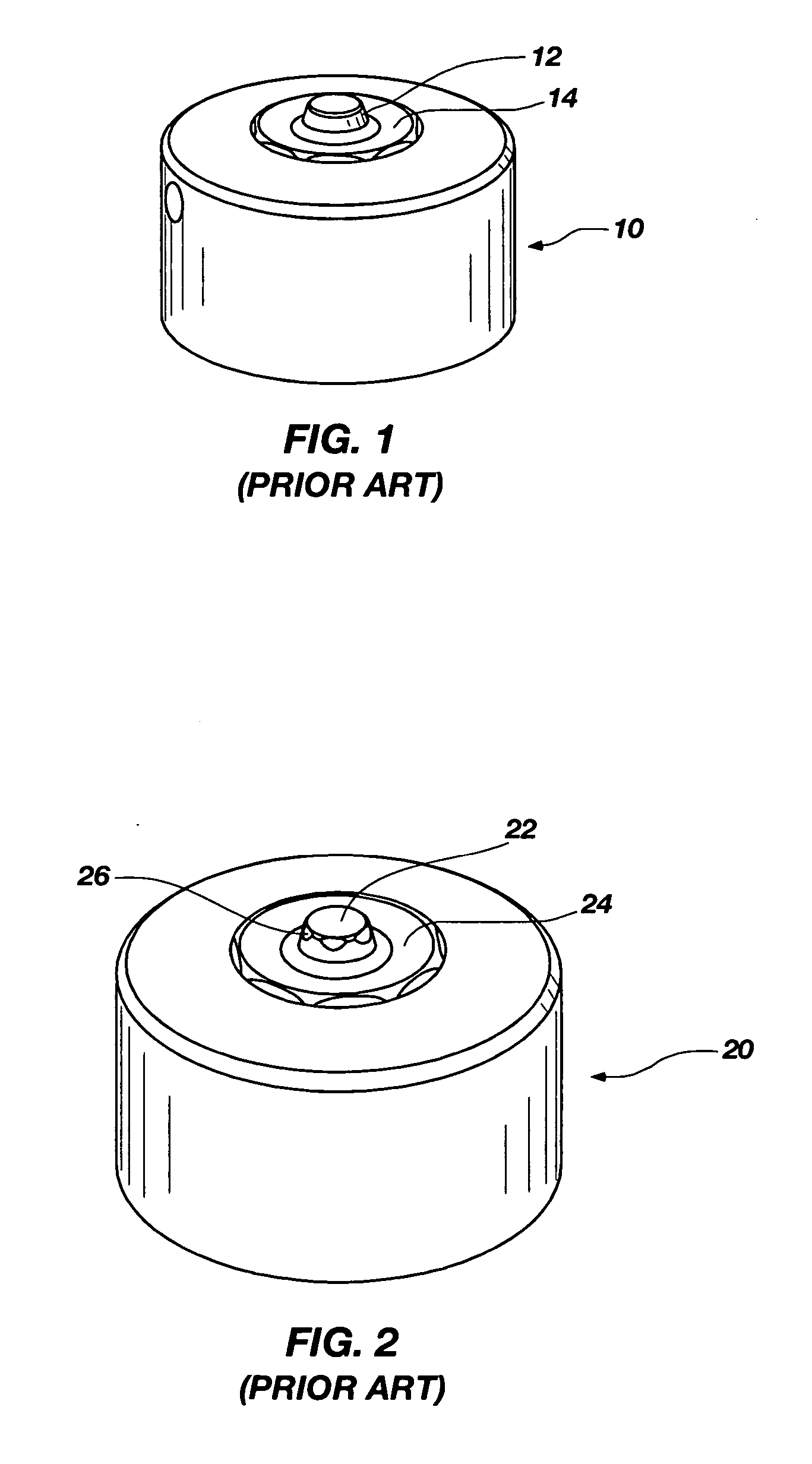
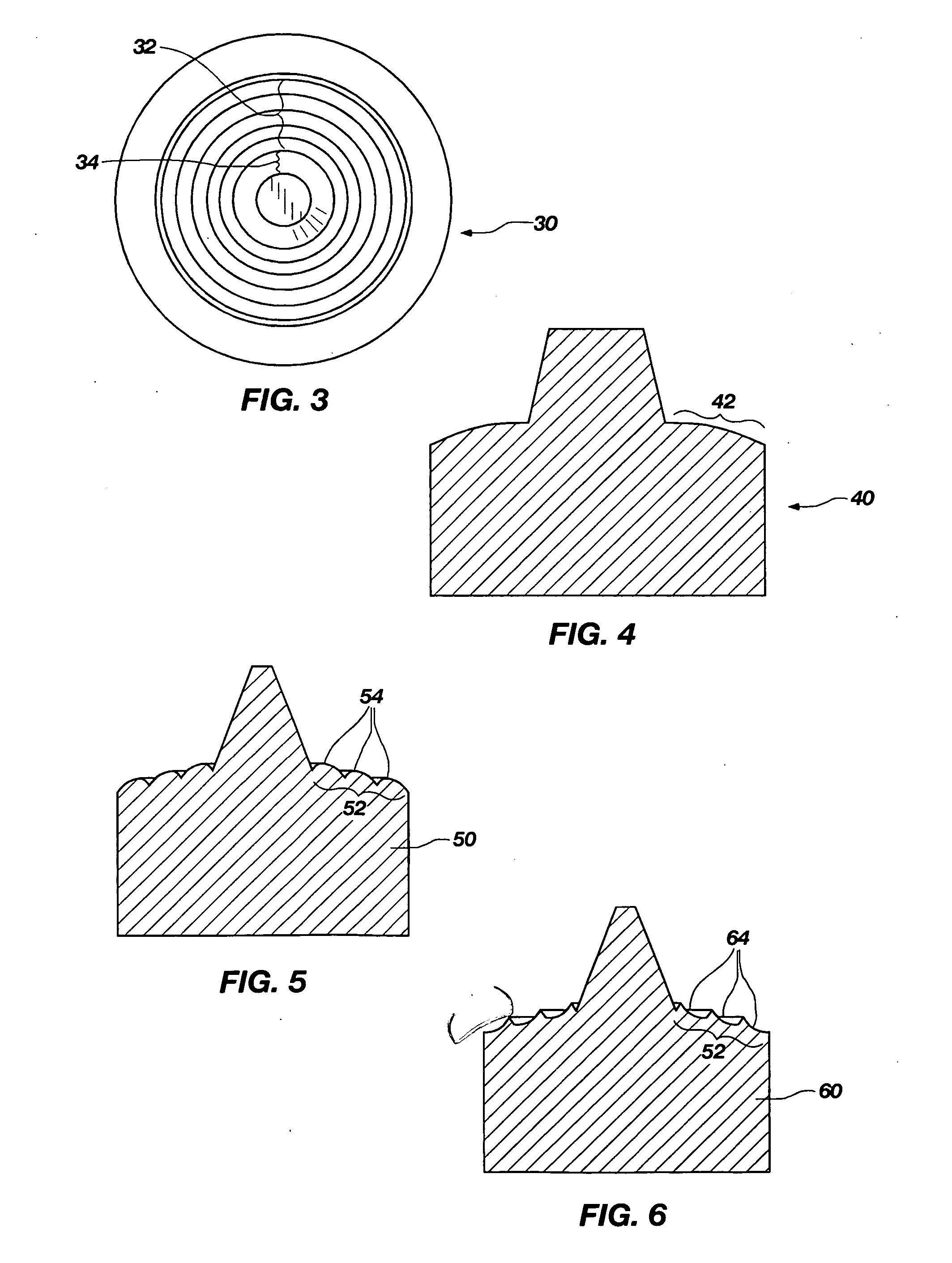
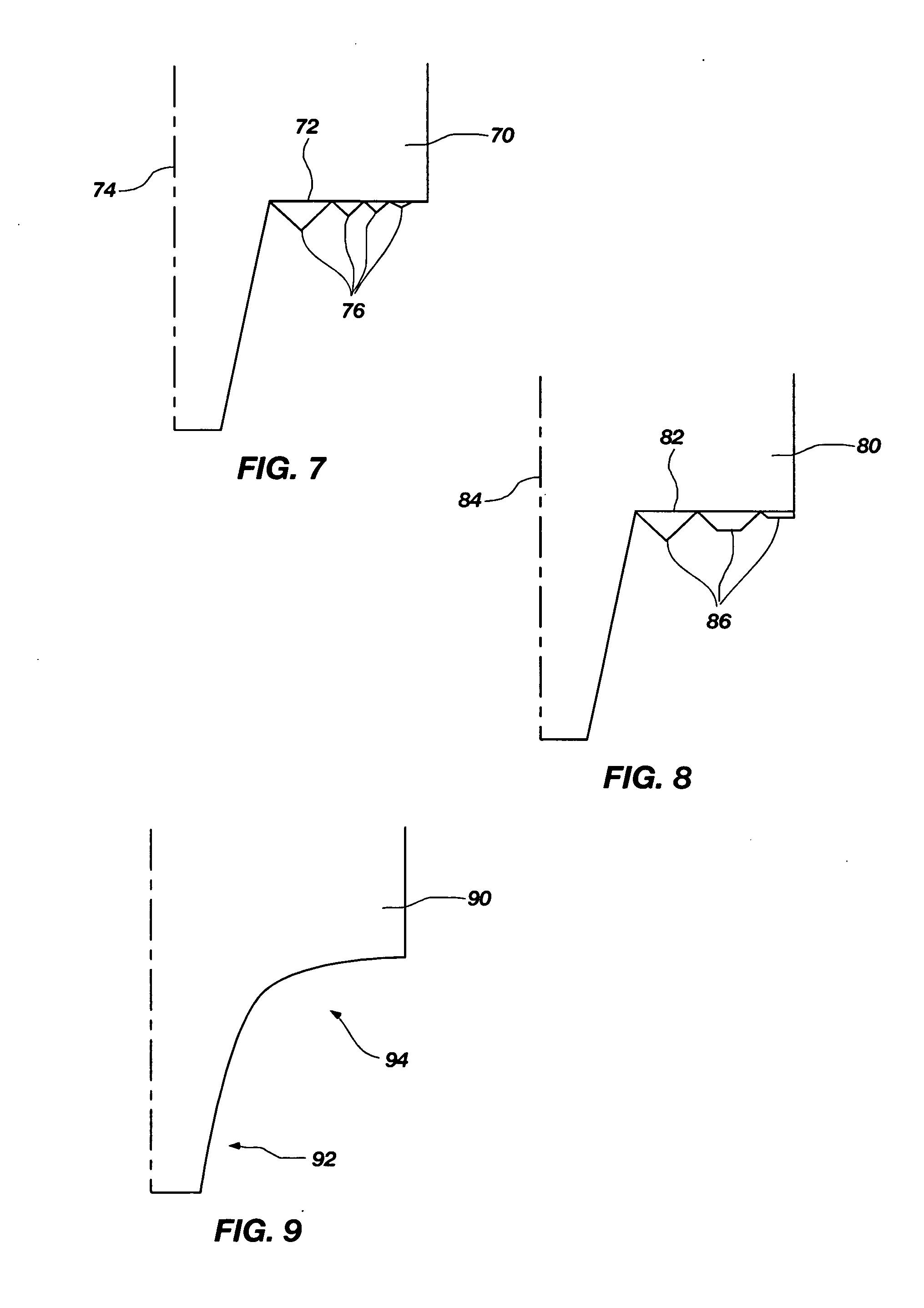
[0032] Reference will now be made to the drawings in which the various elements of the present invention will be given numerical designations and in which the invention will be discussed so as to enable one skilled in the art to make and use the invention. It is to be understood that the following description is only exemplary of the principles of the present invention, and should not be viewed as narrowing the claims which follow.

[0033] Tools designed for friction stirring (and thus all of the friction processes including FSP, FSW, FSM, and FSSW) of HSTM are quite expensive due to high costs of exotic raw materials and extensive finishing operations. These costs make it expensive and impractical to take a trial and error approach to tool design. A systematic methodology using finite element analysis and design of experiments was developed to determine design criteria for tool geometries to be used in processing of HSTM.

[0034] Beginning with a known tool geometry from the prior ar...


PUM

PropertyMeasurementUnit
Temperatureaaaaaaaaaa
Flow rateaaaaaaaaaa
Surfaceaaaaaaaaaa

Abstract

A method of selecting a geometry for a friction stirring tool, said tool having a melting point that is higher than the workpiece material, wherein the tool is placed in motion against the workpiece to generate heat in the workpiece such that workpiece material is transported in surface features of the tool, and wherein surface features manage workpiece material flow around the tool, and wherein the tool can be used in friction stir processing, friction stir mixing, friction stir welding, and friction stir spot welding of high melting temperature materials or high softening temperature materials.

Description

CROSS REFERENCE TO RELATED APPLICATIONS [0001] This document claims priority to, and incorporated by reference all of the subject matter included in the provisional patent application docket number 3348.SMII.PR, having Ser. No. 60 / 689,281 and filed on Jun. 10, 2005.BACKGROUND OF THE INVENTION [0002] 1. Field Of the Invention [0003] This invention relates generally to solid state processing of high softening temperature materials (HSTM) through friction stirring (FS), including friction stir processing (FSP), friction stir mixing (FSM), friction stir welding (FSW), and friction stir spot welding (FSSW). The invention relates more specifically to selecting the geometry of the friction stirring tool that is used to perform all of the friction processes named above. This document will refer to specific processes, but all of the above named friction processes should be considered to be within the scope of whatever process is specifically being discussed. [0004] 2. Description of Related ...

Claims


Application Information

Patent Timeline
IPC IPC(8): A47J36/02
CPCB23K20/1255B23K2203/02B23K20/22B23K2103/02
Inventor STEEL, RUSSELL J.PACKER, SCOTT M.SORENSEN, CARL D.NELSON, TRACY W.FLAK, RICHARD A.
Owner MAZAK CORP
Learn More