
Optical filter, method of manufacturing optical filter, optical system, and imaging apparatus

a technology of optical filters and optical systems, applied in the field of optical filters, can solve the problems of reduced resolution and image deterioration, increased cost, and increased cos

Inactive Publication Date: 2006-12-28
OLYMPUS CORP
View PDF8 Cites 94 Cited by
  • Summary
  • Abstract
  • Description
  • Claims
  • Application Information

AI Technical Summary

Benefits of technology

The present invention provides an imaging apparatus with an optical system made of resin, such as plastic, and an infrared-cut coating applied to at least one face of the optical element. This results in improved image quality and reduced glare. The invention also provides an optical filter with an infrared-cut layer that reflects infrared light and an antireflection layer formed on the other surface of the substrate. Additionally, the invention provides an imaging apparatus with a prism member having a reflective surface with a rotationally asymmetric shape and a protection member that protects the electronic imaging device. The technical effects of the invention include improved image quality, reduced glare, and improved protection of the electronic imaging device.

Problems solved by technology

Reduced resolution and image deterioration are caused by the received infrared light.
Also, since it is necessary to maintain a certain spacing between the filter and lenses on either side thereof, there is a problem in that the overall length of the optical system becomes too large.
In addition, since the infrared-cut filter is provided separately from the optical system, an additional cost is required.
However, the conventional technologies described above have the following requirements and problems.
Second, when applying an infrared-cut coating, there is a certain amount of error in the film thickness of each layer from the design value due to environmental variations, such as changes in temperature, humidity, and pressure.
Therefore, the film thickness error is larger than in an AR coating, and defective products are often produced, resulting in the problem of decreased yield.
Furthermore, when using a reflection-type infrared-cut filter in which an infrared-cut coating for cutting infrared light is applied to the filter surface, a known problem is that the wavelength region that is cut differs when the light is incident perpendicularly and when it is incident at an angle.
Therefore, when the infrared-cut filter is combined with a coaxial optical system that is compact in the optical-axis direction, the angle of incidence of light tends to be different between the central region and the distal regions of the infrared-cut filter, resulting in the problem that color nonuniformity occurs at the central region and the distal regions in an image acquired by the CCD or CMOS device.
In other words, if the filter is made thicker, more infrared light can be cut, but then it becomes difficult to reduce the thickness of the imaging optical system.
Conversely, if the filter is made thinner, the imaging optical system can be reduced in thickness, but there is a drawback in that the amount of infrared light that can be cut is small.

Method used


Image

  • Optical filter, method of manufacturing optical filter, optical system, and imaging apparatus
  • Optical filter, method of manufacturing optical filter, optical system, and imaging apparatus
  • Optical filter, method of manufacturing optical filter, optical system, and imaging apparatus

Examples


first embodiment

[0358] Next, an infrared-cut filter according to a first embodiment of the present invention will be described with reference to the drawings.

[0359]FIG. 38 is a diagram depicting the structure of an infrared-cut filter 501A according to this embodiment.

[0360] As shown in FIG. 38, the infrared-cut filter (optical filter) 501A is roughly formed of two infrared-absorbing filters that absorb infrared, that is, an infrared-absorbing filter (first substrate) 503a and an infrared-absorbing filter (second substrate) 503b, an infrared-cut coating (infrared-cut layer) 505a that reflects infrared, and an antireflection coating 507 that suppresses the reflection of light.

[0361] The infrared-absorbing filters 503a and 503b are plate-like members formed of glass or a resin such as plastic; one example is Lumimcle (registered trademark) from Kureha Chemical Industry Co., Ltd.

[0362] The transmittance (T %) versus wavelength of the infrared-absorbing filters 503a and 503b used in this embodiment...

second embodiment

[0387] Next, an infrared-cut filter according to a second embodiment of the present invention will be described with reference to the drawings.

[0388]FIG. 41 is a diagram for explaining the structure of the infrared-cut filter 501B of this embodiment.

[0389] Components that are the same as those in the first embodiment are assigned the same reference numerals and a description thereof shall be omitted.

[0390] As shown in FIG. 41, the infrared-cut filter (optical filter) 501B roughly includes three infrared-absorbing filters (substrates) 503a, 503b, and 503c that absorb infrared light, an infrared-cut coatings (infrared-cut layer) 505b that reflect infrared light, and antireflection coatings 507 that suppress the reflection of light.

[0391] The infrared-absorbing filter 503c is made of the same material and has the same shape as the infrared-absorbing filters 503a and 503b, and the transmittance (T %) versus wavelength is also the same.

[0392] The infrared-cut coatings 505b are forme...

third embodiment

[0396] Next, an infrared-cut filter according to a third embodiment of the present invention will be described with reference to the drawings.

[0397]FIG. 43 is a diagram depicting the structure of an infrared-cut filter 501C of this embodiment.

[0398] Components that are the same as those in the first embodiment are assigned the same reference numerals, and a description thereof shall be omitted.

[0399] As shown in FIG. 43, the infrared-cut filter (optical filter) 501C roughly includes two infrared-absorbing filters 503a and 503b that absorb infrared light and an infrared-cut coating 505a that reflects infrared light.

[0400] The method of fabricating the infrared-cut filter 501C is the same as that of the first embodiment, except that an antireflection coating is not formed, and a description thereof is thus omitted.

[0401] Moreover, since the effects of the infrared-cut filter 501C are also the same as those of the first embodiment, except for the absence of the antireflection coat...


PUM


Abstract

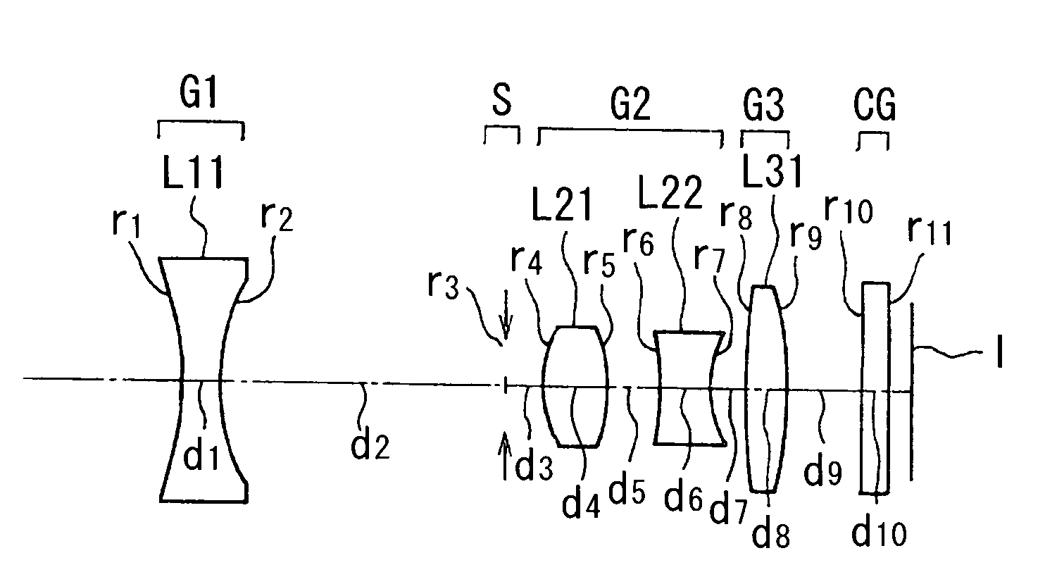
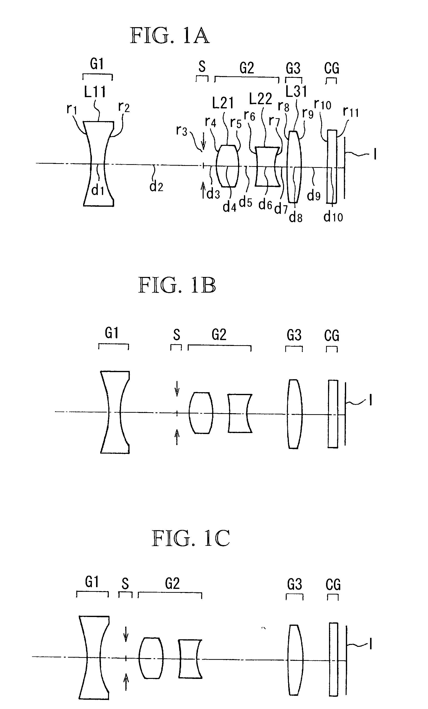
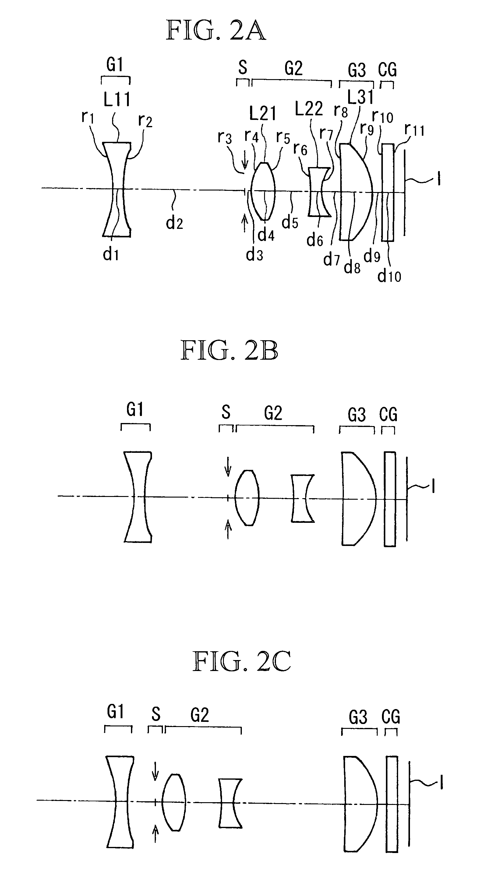
An imaging apparatus comprises an optical system including a plurality of optical elements having finite refractive power and an electronic imaging device disposed at an image side of the optical system. At least one of the plurality of optical elements is made of resin, and an infrared-cut coating is applied to at least one face of the optical element that is made of resin.

Description

BACKGROUND OF THE INVENTION [0001] 1. Field of the Invention [0002] The present invention relates to an optical system having a plurality of optical elements and to an imaging apparatus provided therewith, and relates to an optical system having a plurality of optical elements, such as lens components and prisms, for example, and to an imaging apparatus provided therewith, such as an imaging module for a digital camera or mobile telephone. More specifically, the present invention relates to an optical system in which an infrared-cut coating is applied to refractive surfaces of optical elements, to an optical filter, to a manufacturing method of an optical filter, and to an imaging apparatus provided therewith. [0003] This application is based on Japanese Patent Applications Nos. 2004-235070, 2004-261301, 2005-033680, 2005-033684, and 2005-033694, the contents of which are incorporated herein by reference. [0004] 2. Description of Related Art [0005] Recently, digital video cameras, d...

Claims


Application Information

Patent Timeline
Patent Type & Authority Applications(United States)
IPC IPC(8): G02B27/00
CPCG02B5/282H04N5/2254G02B13/009G02B13/004H04N23/55
Inventor IYAMA, NORIYUKIHOSOKAWA, KAZUYUKIKAWAMATA, KENTOYOHARA, NOBUYOSHISAKAMOTO, JOJI
Owner OLYMPUS CORP
Learn More