Variable magnification optical system

a magnification optical system and variable magnification technology, applied in the field of variable magnification optical systems, can solve the problems of hardly considered to be achieving a wide angle, hardly considered to be achieving a satisfactory balance, and conventional zoom lens systems proposed in patent documents 3 and 4 are hardly considered to achieve a wide angle. , to achieve the effect of wide angle, compact size and higher performan

Inactive Publication Date: 2006-12-28
KONICA MINOLTA PHOTO IMAGING
View PDF4 Cites 27 Cited by
  • Summary
  • Abstract
  • Description
  • Claims
  • Application Information

AI Technical Summary

Benefits of technology

[0011] In view of such a condition, the present invention has been made, and it is an object of the present invention to provide an variable magnification optical system that is compact in size and can provide a high performance while achieving a wide angle and an ultrahigh magnification variation ratio, and also to provide an image-taking apparatus provided therewith.
[0014] According to the present invention, in a variable magnification optical system with a four lens units including: from an object side, a positive, a negative, a positive, a positive lens units, the optical power of the first lens unit and the average refractive index of the second lens unit, and the like satisfies predetermined conditions. This permits achieving a wider angle and an ultrahigh magnification variation ratio while achieving a more compact size and a higher performance. The use of the image taking apparatus according to the present invention for a device, such as digital camera or the like can contribute to slimming down, weight saving, downsizing, cost reduction, performance enhancement, function enhancement, and the like of this device.

Problems solved by technology

However, the conventional zoom lens systems proposed suffer from difficulties in simultaneously satisfying such mutually contradictory demands for a higher magnification variation ratio, a more compact size, a higher performance, and for a wider angle.
The zoom lens system proposed in patent document 2 has a magnification variation ratio as high as ×20, but has a field angle of 70 degrees or less, which is hardly considered to be achieving a wide angle.
The zoom lens systems proposed in patent documents 3 and 4 are also hardly considered to be achieving satisfactory balance among a magnification variation ratio, an optical performance, a lens full length, and the like.

Method used


Image

  • Variable magnification optical system
  • Variable magnification optical system
  • Variable magnification optical system

Examples


examples

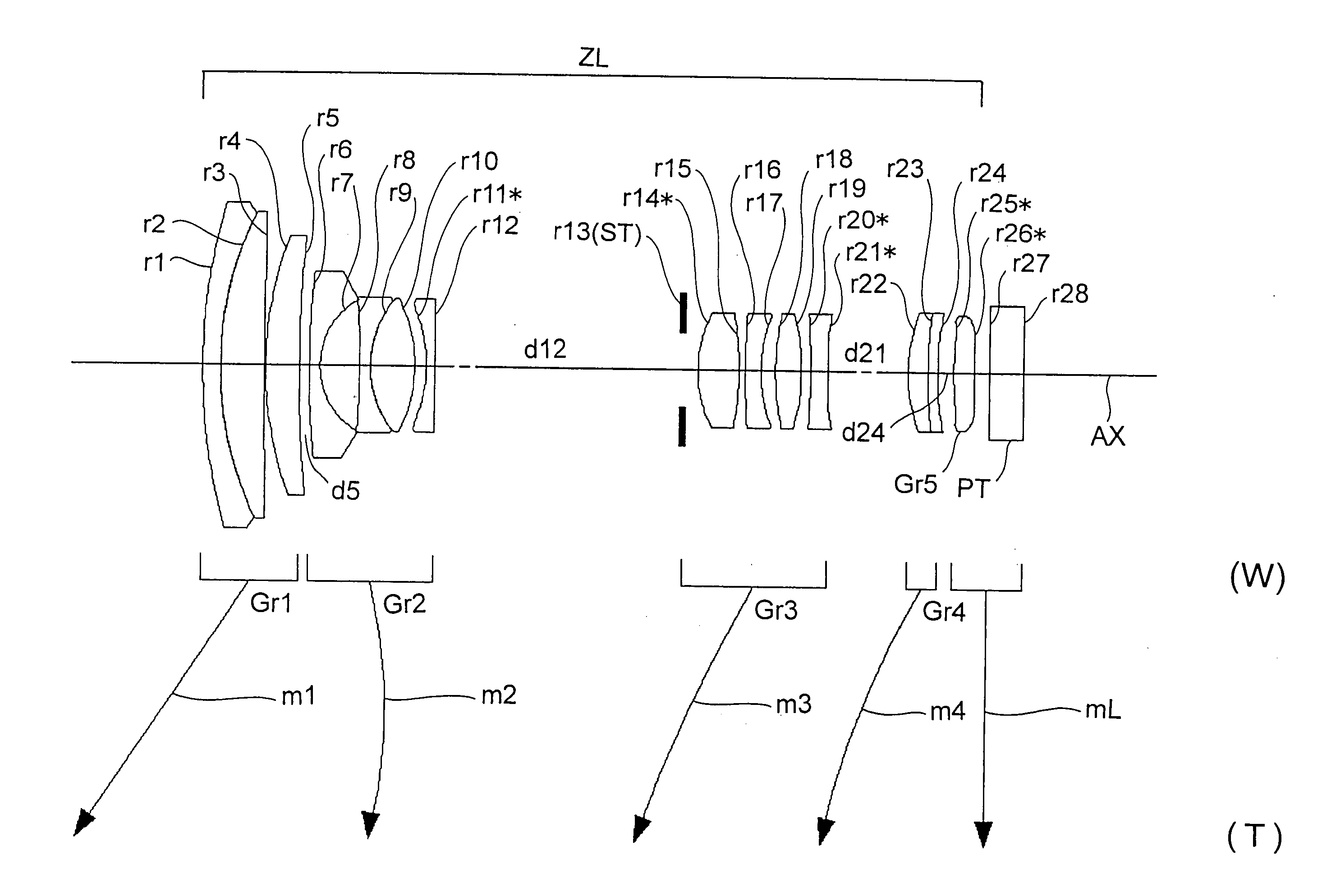
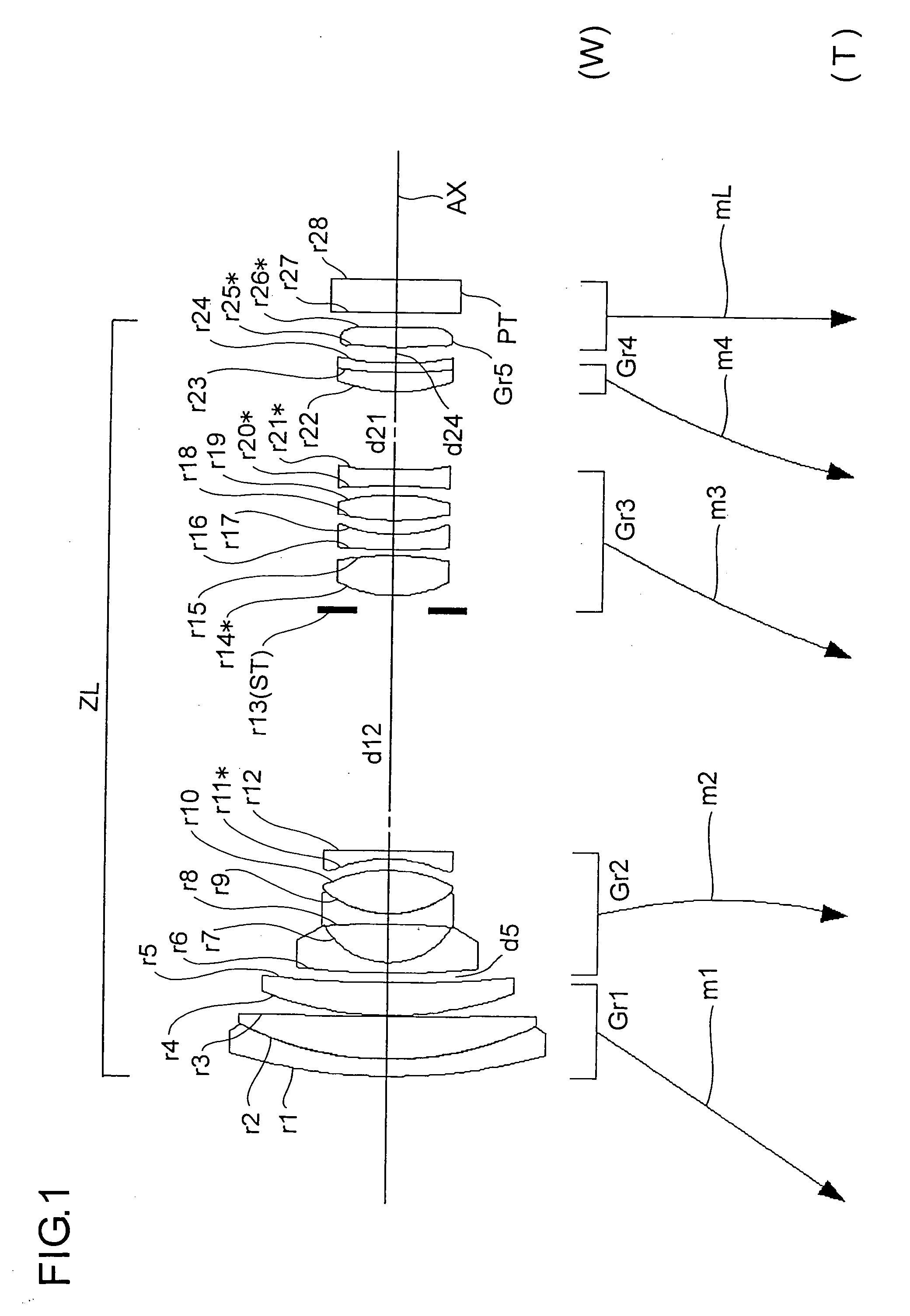
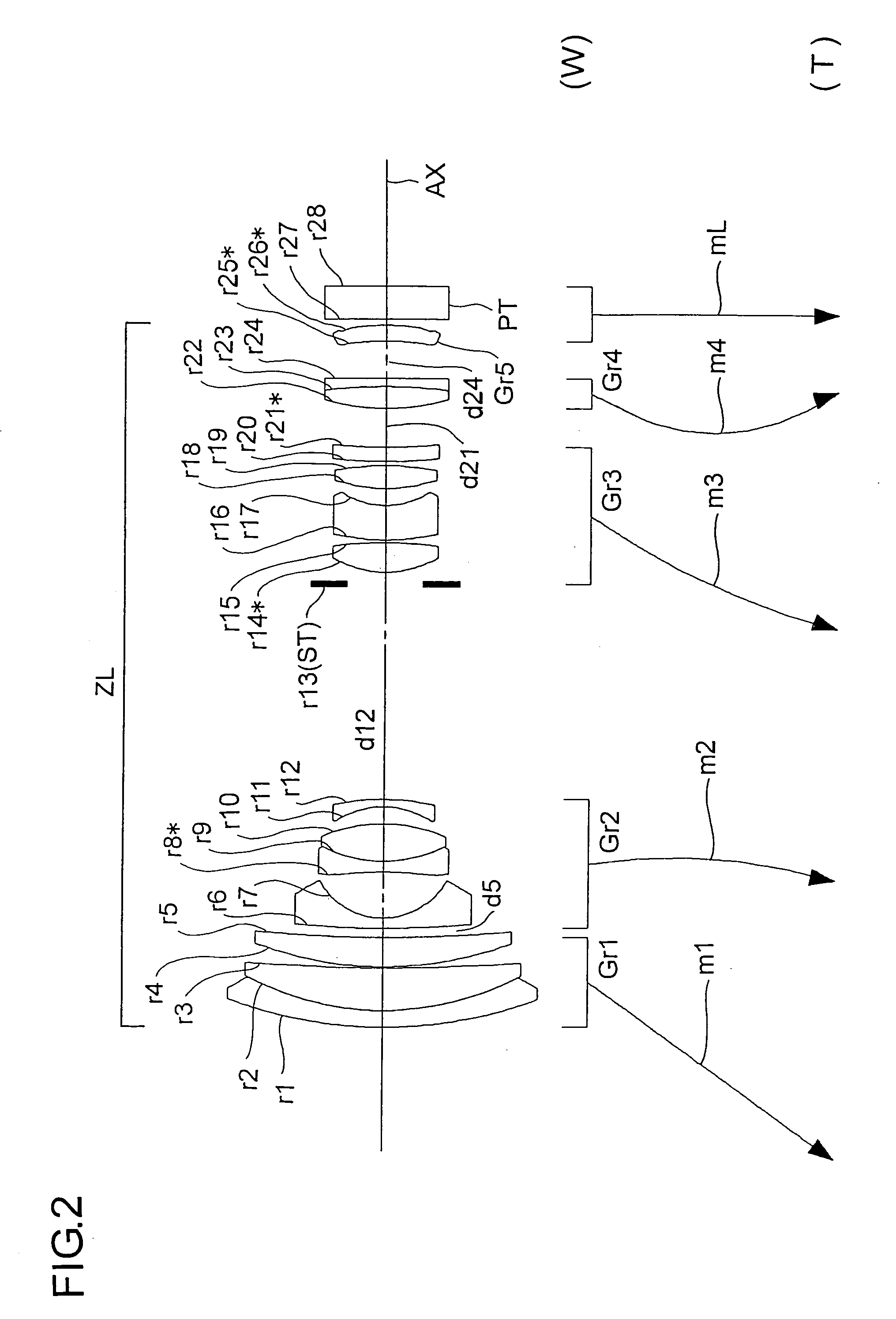
[0066] Hereinafter, practical examples of the zoom lens system embodying the present invention will be presented with reference to their construction data and other data. Examples 1 to 5 presented below are numerical examples corresponding respectively to the first to fifth embodiments described above. Thus, the optical construction diagrams (FIGS. 1 to 5) showing the first to fifth embodiments also show the lens constructions of Examples 1 to 5, respectively.

[0067] Tables 1 to 10 show the construction data of Examples 1 to 5. Table 11 shows the values for the conditional formulae as actually observed in each example. In the basic optical construction shown in Tables 1, 3, 5, 7, and 9 (where i represents the surface number), ri (i=1, 2, 3, . . . ) represents the radius of curvature (mm) of the i-th surface counted from the object side; di (i=1, 2, 3, . . . ) represents the axial distance (mm) between the i-th and (i+1)th surfaces counted from the object side; Ni (i=1, 2, 3, . . . )...


PUM


Abstract

A variable magnification optical system for forming an optical image of an object on a light-receiving surface of an image sensor with variable magnification includes: from the object side, at least a first lens unit having a positive optical power, a second lens unit having a negative optical power, a third lens unit having a positive optical power, and a fourth lens unit having a positive optical power. In magnification variation from the wide angle end to the telephoto end, at least the first lens unit moves. Conditional formulae (1) and (2) below are fulfilled: (1) 6.0<fl / fw<20.0 and (2) 1.83<Ndave, where fl represents the focal length of the first lens unit, fw represents the focal length of the entire system at the wide angle end, and Ndave represents the average refractive index for a d-line among all lens elements included in the second lens unit.

Description

[0001] This application is based on Japanese Patent Application No. 2005-187555 filed on Jun. 28, 2005, the contents of which are hereby incorporated by reference. BACKGROUND OF THE INVENTION [0002] 1. Field of the Invention [0003] The present invention relates to a variable magnification optical system. More particularly, the present invention relates to a variable magnification optical system suitable for, for example, a digital camera or a digital appliance equipped with an image capturing capability that capture an image of a subject with an image sensor, especially a compact zoom lens system that provides a wide angle and a high magnification variation ratio, and to an image-taking apparatus provided therewith. [0004] 2. Description of Related Art [0005] In recent years, as personal computers become increasingly widespread, digital cameras which permits easy acquisition of images have been becoming more and more popular. Consequently, there has been a demand for a more compact ...

Claims


Application Information

Patent Timeline
Patent Type & Authority Applications(United States)
IPC IPC(8): G02B15/14
CPCG02B15/173G02B15/144113G02B15/145129
Inventor TERADA, MAMORUNAKATANI, TORU
Owner KONICA MINOLTA PHOTO IMAGING
Why Eureka
Try Eureka