Annular light guide

a technology of annules and light guides, applied in the direction of lighting and heating apparatus, mechanical control devices, instruments, etc., can solve the problems of poor illumination efficiency, lack of brightness, and inability to be utilized, so as to improve illumination efficiency, improve illumination efficiency, and improve illumination efficiency.

Active Publication Date: 2006-12-28
ALPS ALPINE CO LTD
View PDF8 Cites 33 Cited by
  • Summary
  • Abstract
  • Description
  • Claims
  • Application Information

AI Technical Summary

Benefits of technology

[0017] In addition, if collective lenses that have a convex lens shape and refract light from the light source to guide the light to the light outlet are formed in part of the inner wall surface of the light inlet in which the inner wall demarcates the cavity, much of light incident from the light source to the collective lenses can be utilized as illumination light, so that it is possible to improve the illumination efficiency further.
[0018] If outward projected fringes are formed on an outer wall surface of the other side of a light inlet (i.e., the opposite side to a light outlet side) so as to extend in the through-thickness direction, light emitted from a light source in a direction where the light outlet is not present can be easily utilized as illumination light, so that it is possible to improve the illumination efficiency further. In this case, if the outward projected fringes are formed such that one part of surface closer to a symmetry line passing through the center of the light inlet and the light outlet is broader than the other part of surface farther from the symmetry line, the amount of light that turns back in a direction of the light source is reduced, and also the amount of light that travels to the light outlet is increased, so that it is possible to improve the illumination efficiency further.
[0019] If inward projected fringes are formed in a region facing the other side (the opposite side to the light outlet side) on an inner wall surface of the light inlet demarcating a cavity so as to extend in the through-thickness direction such that light from the light source is refracted by the inward projected fringes to travel in a predetermined direction of said other side, it is possible to refract light incident from the light source to the inward projected fringes in undesired directions where it is difficult to guide light to the light outlet, to thereby change the direction of the light. Therefore, it is possible to improve the illumination efficiency further.
[0020] The annular light guide is constructed such that a light source is disposed in a cavity of a light inlet, so that it is possible to utilize, as illumination light, light emitted from the light source in a direction where the light outlet is not present without leaking from the external wall surface of the light inlet. Therefore, it is possible to efficiently utilize light from the light source and substantially improve the illumination efficiency.

Problems solved by technology

Therefore, light from the light source 7 which is not incident to the side surface 5c can not be utilized, so that there has been a problem that illumination efficiency is poor.
As the result, only part of light from the light source 7 can be used as illumination light for the illumination area, thus causing a lack of brightness and higher power consumption of the light source 7.

Method used


Image

  • Annular light guide
  • Annular light guide
  • Annular light guide

Examples


Embodiment Construction

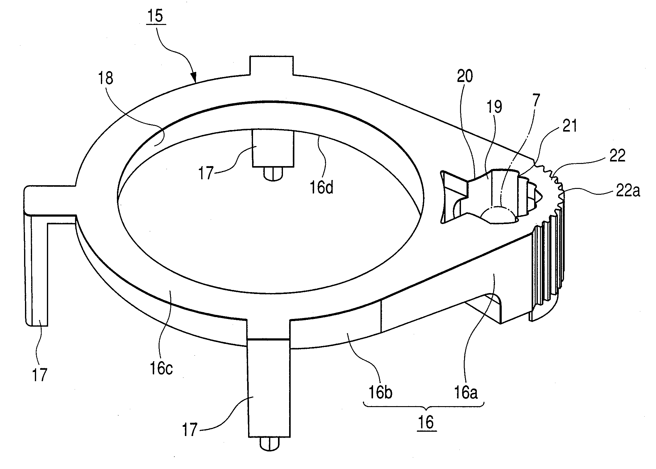
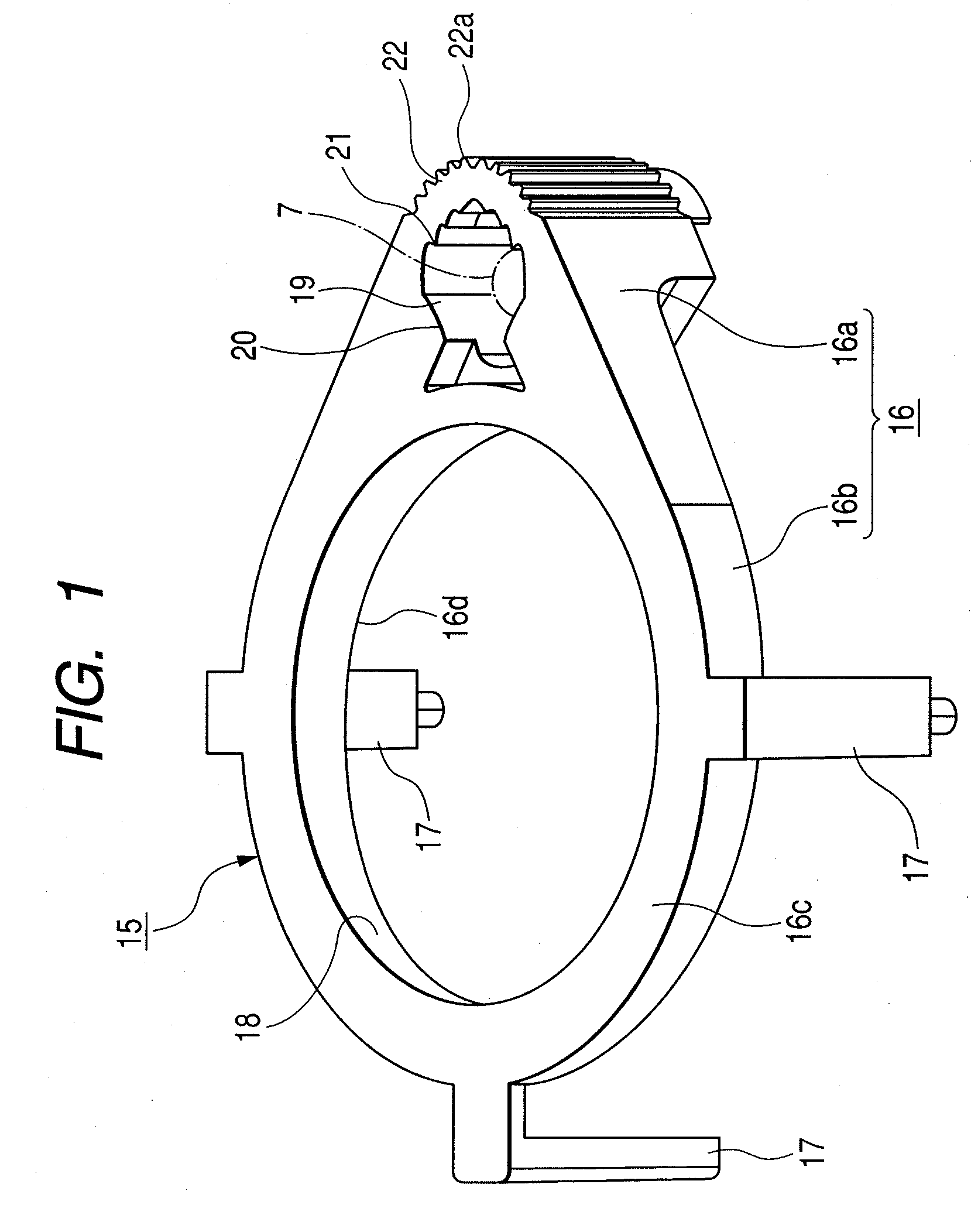
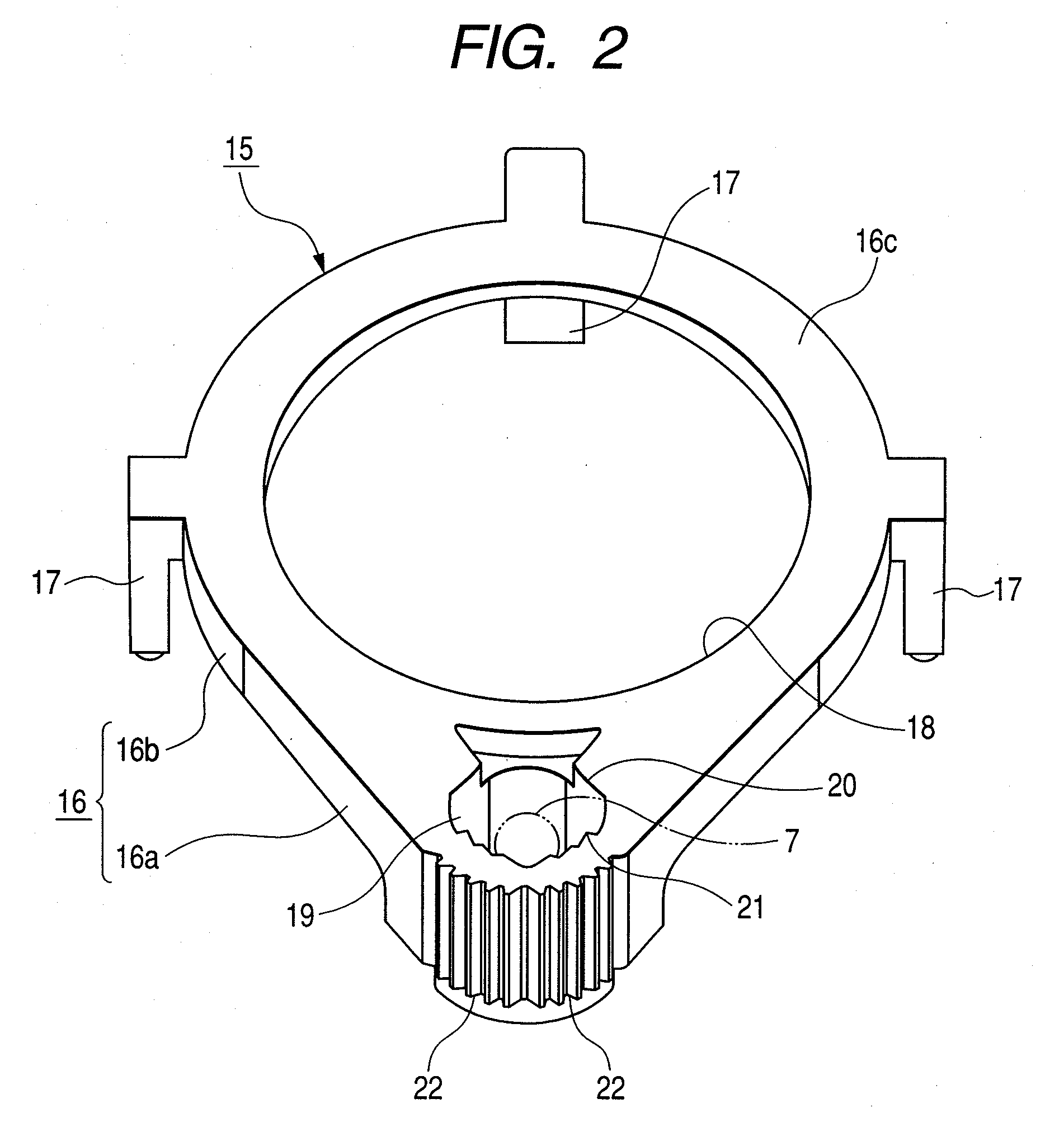
[0027] Hereinafter, embodiments will be described with reference to the attached drawings. FIG. 1 is a perspective view showing an annular light guide. FIG. 2 is a perspective view showing the annular light guide viewed from another direction. FIG. 3 is a sectional view of the annular light guide. FIG. 4 is a plan view showing a primary part of a light inlet of the annular light guide.

[0028] The annular light guide 15 shown in these figures is a molded product made of highly optically transparent material such as acrylic resin, and is formed such that L-shaped mounting legs protrude at plural places of an annular body 16 which is an integrated combination of a light inlet 16a and a light outlet 16b. A shaft inserting hole 18 is formed in the annular body 16, and the toric part around the shaft inserting hole 18 corresponds to the light outlet 16b, and wide and thick part swelling out laterally from the light outlet 16b corresponds the light inlet 16a. In other words, the light outl...


PUM


Abstract

An annular light guide is provided. The annular light guide is made of optically transparent material, and is provided with an annular body that is an integrated combination of a light inlet and a light outlet. A light source is disposed in a cavity formed in the light inlet. Illumination light is emitted from the front surface 16c of the light outlet.

Description

[0001] This application claims the benefit of the Japanese Patent Application No. 2005-183780 filed on Jun. 23, 2005, which is hereby incorporated by reference. BACKGROUND [0002] 1. Field [0003] An annular light guide is provided. The annular light guide is disposed in the back of a face plate or the like of rotary operation type electrical components. The electrical components have an illumination area along the circumferential direction and is used for illuminating the illumination area while guiding light from a light source. [0004] 2. Related Art [0005] Conventionally, rotary operation type electrical components e are used in in-car air conditioner systems, in-car audio systems and the like. These systems use an illumination system adopted so that rotational position of a rotary knob is rotated by a passenger and is visible even in a dark place. In the illumination system, an annular thin face plate with an indicator is provided along the circumferential direction and is dispose...

Claims


Application Information

Patent Timeline
Patent Type & Authority Applications(United States)
IPC IPC(8): F21V7/04
CPCG02B6/0016G05G1/105G02B6/0021G02B6/0018
Inventor NISHIYAMA, YOSHINORIKOBAYASHI, AYUMU
Owner ALPS ALPINE CO LTD
Why Eureka
Try Eureka