Multiple optical assembly for a led lighting device, and red lighting device comprising such an optical assembly

Inactive Publication Date: 2006-12-28
FRAEN CORPORATION
View PDF8 Cites 74 Cited by
  • Summary
  • Abstract
  • Description
  • Claims
  • Application Information

AI Technical Summary

Benefits of technology

[0006] The multiple optical assembly according to the invention is highly efficient and compact, and can be produced cheaply and easily. Moreover, the optical surfaces, being separate, do not interfere with one another, thus ensuring optimum performance.
[0007] The lighting device featuring the

Problems solved by technology

Currently available solutions, however, are not yet fully satisfactory in terms of lighting efficiency and straightforward design.
That is, on the one hand, single-LED lights fail to provide for adequ

Method used


Image

  • Multiple optical assembly for a led lighting device, and red lighting device comprising such an optical assembly
  • Multiple optical assembly for a led lighting device, and red lighting device comprising such an optical assembly
  • Multiple optical assembly for a led lighting device, and red lighting device comprising such an optical assembly

Examples


Embodiment Construction

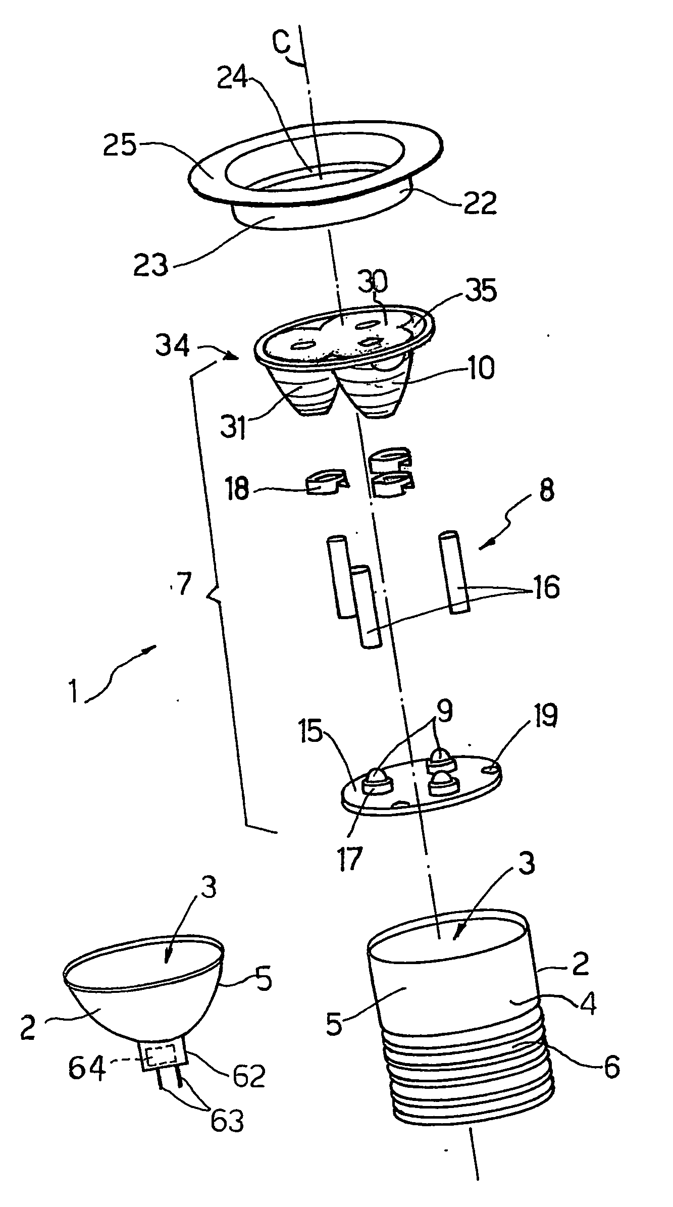
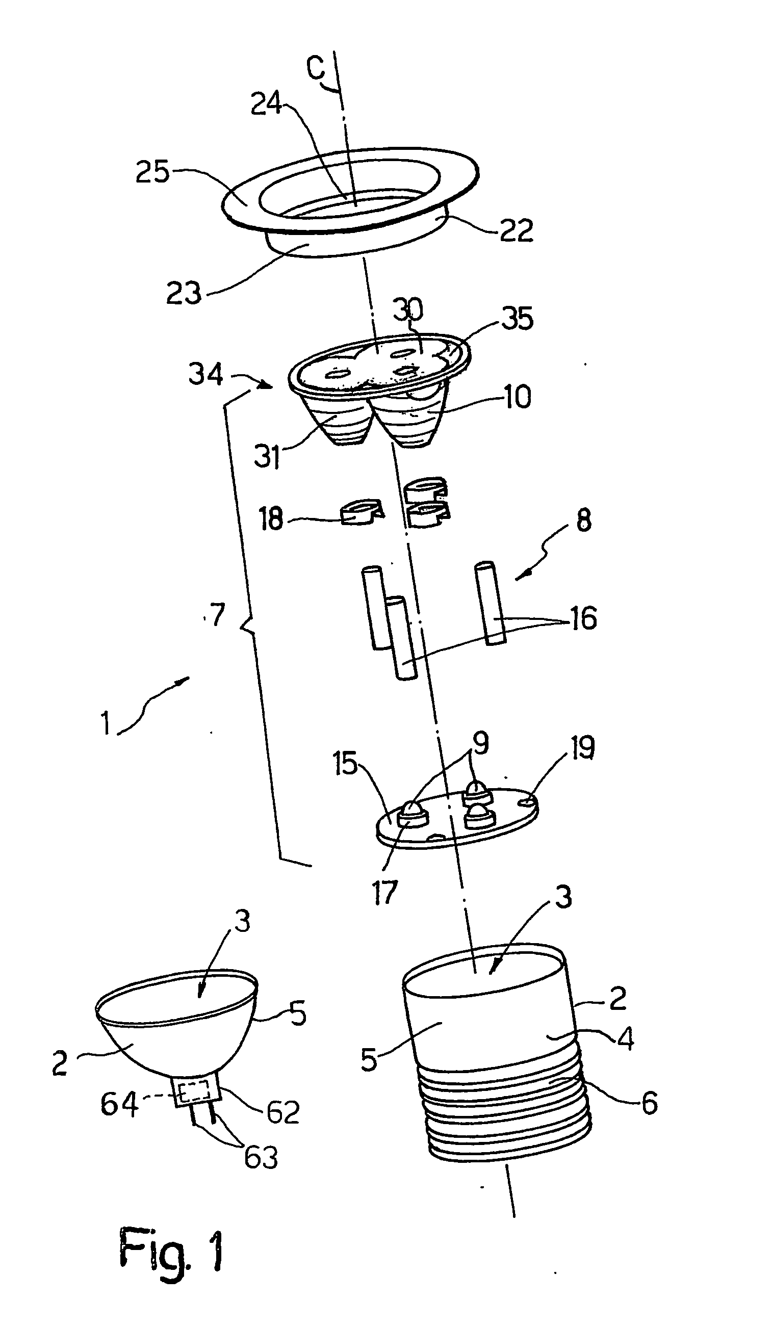
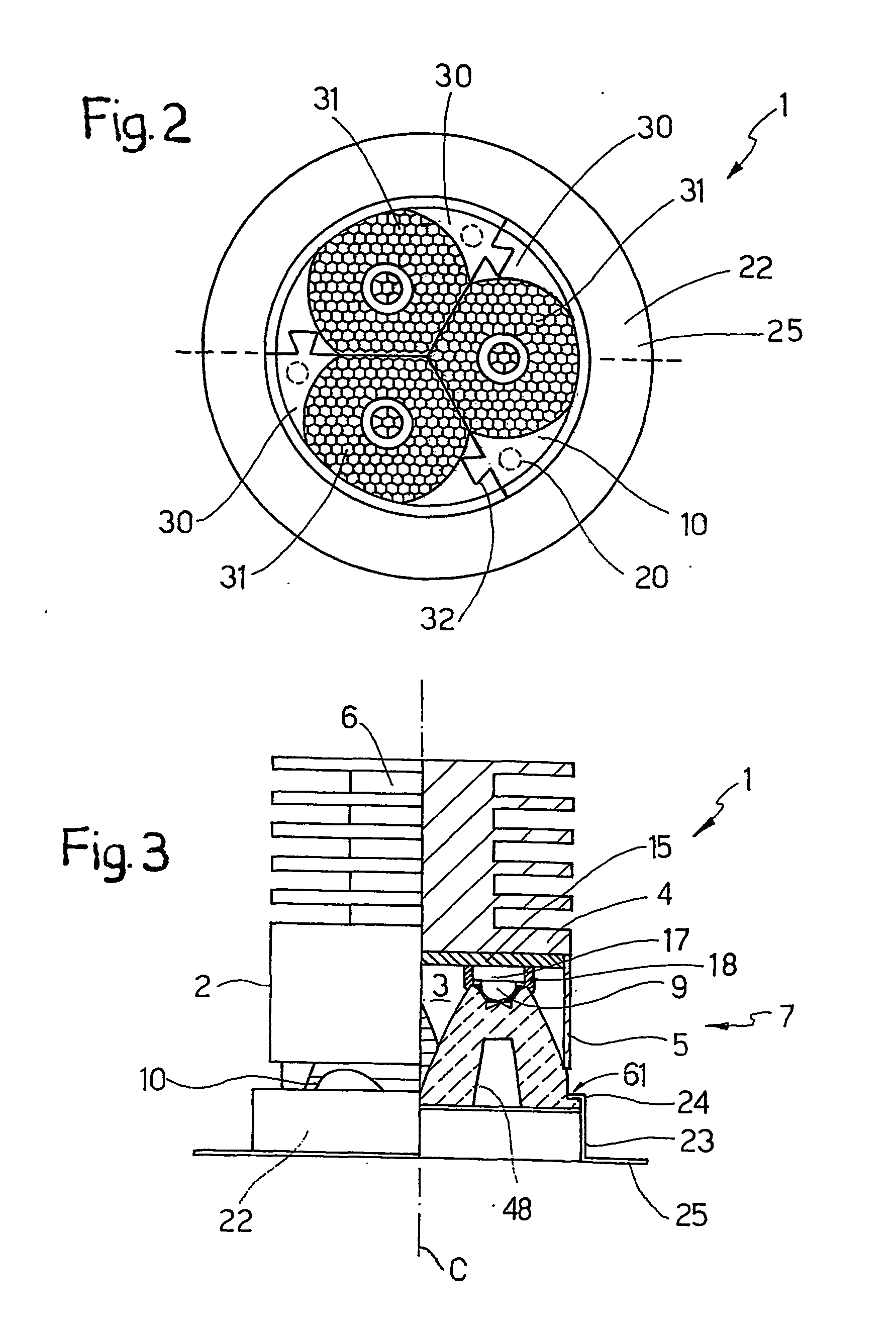
[0015] With reference to FIGS. 1 to 3, a LED lighting device 1, usable in particular as an interior spot light, comprises a casing 2 having an inner, e.g. substantially cylindrical, chamber 3 defined by a bottom wall 4 and a lateral wall 5. A heat dissipator 6 projects axially from bottom wall 4, on the opposite side to chamber 3, and comprises, for example, a central column, from which annular fins extend radially. Chamber 3 houses a lighting module 7 comprising a supporting structure 8 supporting a number of LED's 9 (or other similar type of solid-state light sources), and a multiple optical assembly 10 connected mechanically to LED's 9 by supporting structure 8 and designed to convey the light emitted by LED's 9 in a predetermined pattern.

[0016] Supporting structure 8 comprises a flat plate 15 fitted with LED's 9 and which rests on bottom wall 4; and connecting members 16 for connecting optical assembly 10 axially and circumferentially to plate 15. In the example shown, three co...


PUM


Abstract

A LED lighting device has a number of LED's, and a multiple optical assembly defined by a number of modular units; each modular unit has a total-internal-reflection lens associated with a LED, and the modular units are connected to one another so as the lenses have respective distinct optical reflecting surfaces.

Description

TECHNICAL FIELD [0001] The present invention relates to a multiple optical assembly for a LED lighting device, and to a LED lighting device comprising such an optical assembly. BACKGROUND ART [0002] Of interior lighting devices, standard-size spot lights are widely used, which can be installed in a variety of configurations, and for this reason are of specific shape and size. Typical of these, for example, are MR-16 standard dichroic lights. [0003] Recently, lights of this type have been proposed which, instead of normal quartz-iodine lamps, employ solid-state light sources, in particular light-emitting diodes (LED's). Currently available solutions, however, are not yet fully satisfactory in terms of lighting efficiency and straightforward design. That is, on the one hand, single-LED lights fail to provide for adequate light intensity, whereas, given the limited (standard-imposed) space available, using banks of LED's associated with respective lenses calls for using small, and ther...

Claims


Application Information

Patent Timeline
IPC IPC(8): F21V5/00F21V5/04F21V7/00F21V29/00
CPCF21V5/04F21V7/0091F21V29/004F21V29/767F21V17/10F21V17/104F21Y2101/02F21Y2115/10F21V29/74
Inventor ANGELINI, MARCOBARALDO, NATALEBIGLIATI, CLAUDIASCODES, LUCA
Owner FRAEN CORPORATION
Why Eureka
Try Eureka