Disc drive apparatus

a disc drive and disc drive technology, applied in the direction of digital signal error detection/correction, instruments, recording signal processing, etc., can solve the problems of position errors, inadequate handling of disturbances of the first category, and different control characteristics

Inactive Publication Date: 2006-12-28
KONINKLIJKE PHILIPS ELECTRONICS NV
View PDF9 Cites 2 Cited by
  • Summary
  • Abstract
  • Description
  • Claims
  • Application Information

AI Technical Summary

Problems solved by technology

Position errors may, in practice, be caused by different types of disturbances.
A problem in this respect is that adequately handling disturbances of the first category requires a different control characteristic than adequately handling disturbances of the second category.

Method used


Image

  • Disc drive apparatus
  • Disc drive apparatus
  • Disc drive apparatus

Examples


Embodiment Construction

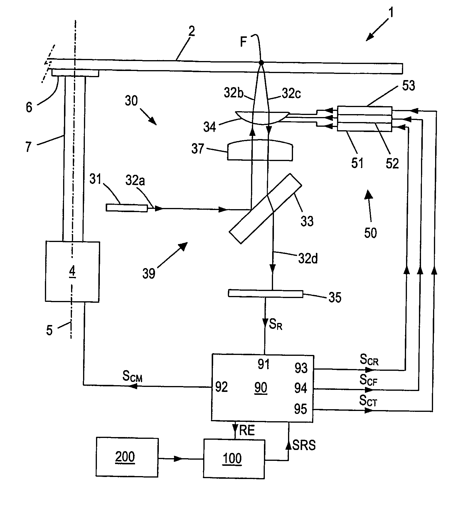
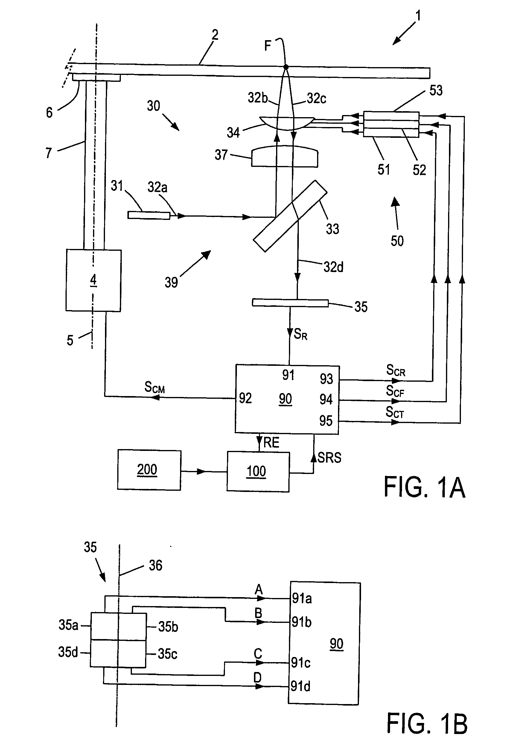
[0030]FIG. 1A schematically illustrates an optical disc drive apparatus 1, suitable for storing information on or reading information from an optical disc 2, typically a DVD or a CD. For rotating the disc 2, the disc drive apparatus 1 comprises a motor 4 fixed to a frame (not shown for sake of simplicity), defining a rotation axis 5.

[0031] The disc drive apparatus 1 further comprises an optical system 30 for scanning tracks (not shown) of the disc 2 by an optical beam. More specifically, in the exemplary arrangement illustrated in FIG. 1A, the optical system 30 comprises a light beam generating means 31, typically a laser such as a laser diode, arranged to generate a light beam 32. In the following, different sections of the light beam 32, following an optical path 39, will be indicated by a character a, b, c, etc added to the reference numeral 32.

[0032] The light beam 32 passes a beam splitter 33, a collimator lens 37 and an objective lens 34 to reach (beam 32b) the disc 2. The l...


PUM

PropertyMeasurementUnit
cut-off frequencyaaaaaaaaaa
diameteraaaaaaaaaa
frequencyaaaaaaaaaa

Abstract

A method is described for detecting a mechanical shock in a disc drive apparatus (1) of a type comprising: scanning means (30) for scanning record tracks of a disc (2) and for generating a read signal (SR); actuator means (50) for controlling the positioning of at least one read / write element (34) of said scanning means; a control circuit (90) for receiving said read signal (SR), deriving at least one error signal (RE) from said read signal, and generating at least one actuator control signal (SCR) on the basis of said error signal. The method comprises the steps of: -determining a shock sensitivity function (SSHOCK) which describes the relationship between shocks (OExT) and said error signal; determining or at least approximating an inverse shock sensitivity function (S-lSHOCK) as the inverse of said shock sensitivity function (SSHOCK);—and applying said inverse shock sensitivity function (Sl-SHOCK)on said error signal.

Description

FIELD OF THE INVENTION [0001] The present invention relates in general to a disc drive apparatus for writing or reading information into or from a storage disc. Although the gist of the invention also applies to magnetic discs, the present invention specifically applies to optical discs, for which reason the invention will hereinafter be described for optical discs, while the corresponding disc drive apparatus will also be indicated as “optical disc drive”. BACKGROUND OF THE INVENTION [0002] As is commonly known, an optical storage disc comprises at least one track, either in the form of a continuous spiral or in the form of multiple concentric circles, of storage space where information may be stored in the form of a data pattern. Optical discs may be read-only type, where information is recorded during manufacturing, which information can only be read by a user. The optical storage disc may also be a writeable type, where information may be stored by a user. For writing informatio...

Claims


Application Information

Patent Timeline
Patent Type & Authority Applications(United States)
IPC IPC(8): G11B20/00G01P15/04G11B5/55G11B7/09G11B19/04G11B21/10
CPCG11B5/5582G11B21/106G11B19/04G11B7/0946G11B5/55G11B21/02G11B21/10
Inventor COOLEN, ROB JACOBUS MATHEUSCREMERS, FRANCISCUS MARIA LAMBERTUSLEENKNEGT, GEORGE ALOIS LEONIEHEERTJES, MARCEL FRANCOIS
Owner KONINKLIJKE PHILIPS ELECTRONICS NV
Why Eureka
Try Eureka