Communication path redundancy protection systems and methods

a protection system and communication path technology, applied in the field of communication, can solve the problems of requiring network re-convergence, several minutes of communication traffic disruption, and remains a significant challenge of how to offer high availability ip services, and achieve the effect of high network availability constraints

Inactive Publication Date: 2006-12-28
ALCATEL LUCENT SAS
View PDF5 Cites 93 Cited by
  • Summary
  • Abstract
  • Description
  • Claims
  • Application Information

AI Technical Summary

Benefits of technology

[0006] Embodiments of the invention provide communication path redundancy protection at an IP gateway for applications, such as VoIP and video applications, having high network availability constraints.

Problems solved by technology

Protection of communication systems to provide reliable service and high availability is an ongoing challenge for operators and service providers.
Other components of a redundancy group, one or more “standby” components, are typically idle until a failure of the active component is detected.
However, despite the extra investment in a second router for every gateway router which is to be protected, an activity switch in VRRP affects routing topology in the backbone IP network, thereby requiring network re-convergence.
This can result in several minutes of communication traffic disruption before full service restoration.
Thus, although VRRP provides a level of protection against gateway router failure, there remains a significant challenge of how to offer high availability IP services.
Service interruption recovery times on the order of minutes are not feasible for IP networks in which mission critical and real-time services such as Voice over IP (VoIP), video services, and web commerce services are to be offered.

Method used


Image

  • Communication path redundancy protection systems and methods
  • Communication path redundancy protection systems and methods
  • Communication path redundancy protection systems and methods

Examples


Embodiment Construction

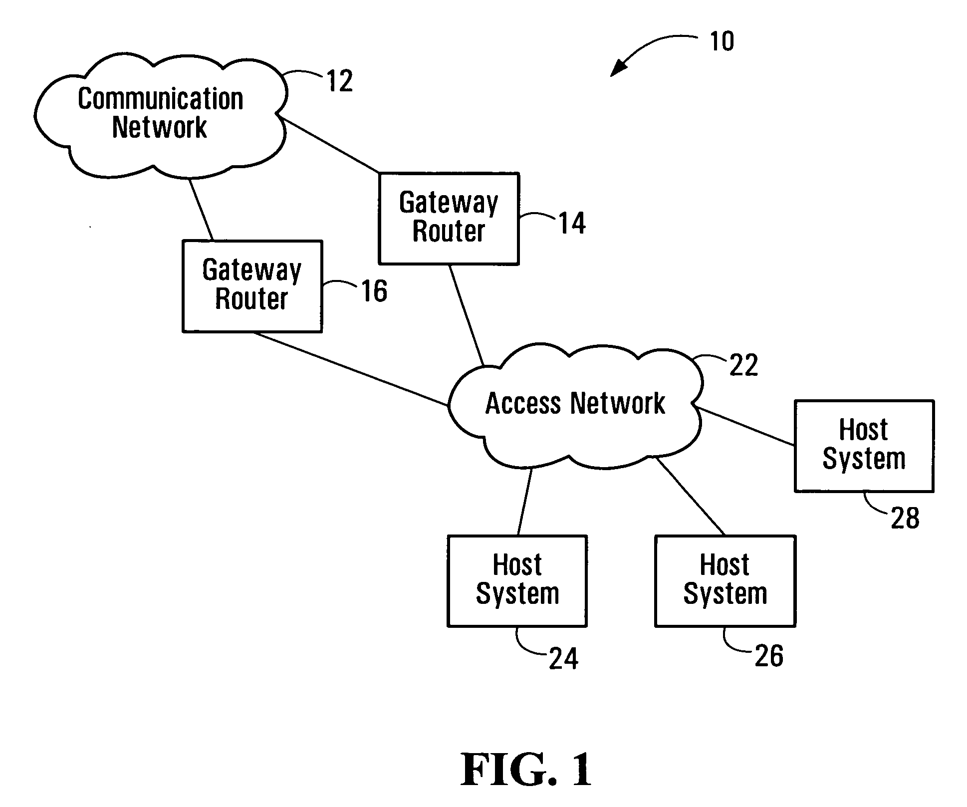
[0031]FIG. 1 is a block diagram of a communication system implementing redundant gateway routers. The communication system 10 includes a communication network 12, redundant gateway routers 14, 16, an access network 22, and host systems 24, 26, 28. In a typical VRRP installation, the communication network 12 is an IP network, the gateway routers 14, 16 are IP routers, the access network 22 is a LAN, and the host systems 24, 26, 28 are IP hosts. Those skilled in the art will be familiar with the components shown in FIG. 1, which are therefore described only briefly herein.

[0032] Dynamic IP routing has been the norm of production network deployment in so-called core networks such as the communication network 12. The access network 22 connected to host systems 24, 26, 28, however, has typically remained a static and default routing environment.

[0033] This scenario is very common in service provider networks. In a service provider network, the host systems 24, 26, 28 may be IP hosts su...


PUM


Abstract

Communication path redundancy protection systems and methods are disclosed. Multiple communication interfaces having a common address support communications on respective communication paths. One of the interfaces or communication paths is selected as an active interface or path for transferring communication traffic. In the event of a fault associated with the active interface or path, another one of the interfaces or paths is selected to become active. The common address allows redundant interfaces to appear as a single interface to other communication equipment, whereas the multiple interfaces provide redundant path protection using a single piece of communication equipment. When embodiments of the invention are implemented in a gateway router of a core communication network, for example, activity switches between redundant access paths have no effect on routing in the core network.

Description

Field of the Invention [0001] This invention relates generally to communications and, in particular, to providing redundancy protection for communication paths in a communication system. BACKGROUND [0002] Protection of communication systems to provide reliable service and high availability is an ongoing challenge for operators and service providers. Equipment redundancy is one example of a common protection scheme. In an equipment redundancy protection system, groups of components which are capable of performing the same functions, or at least common protected functions, are deployed. Only one redundant component of a redundancy group is normally relied upon to perform protected functions at any time, and is generally referred to as the “active” component. Other components of a redundancy group, one or more “standby” components, are typically idle until a failure of the active component is detected. In this event, activity is switched from the failed active component to a standby co...

Claims


Application Information

Patent Timeline
Patent Type & Authority Applications(United States)
IPC IPC(8): H04J3/14
CPCH04L12/2854H04L12/46H04L45/00H04L45/28H04L45/22
Inventor BROTHERSTON, MICHAELCHAN, HANSEN
Owner ALCATEL LUCENT SAS
Why Eureka
Try Eureka