Fuel cell system

a fuel cell and system technology, applied in the field of fuel cell systems, can solve the problems of increasing consumption power, and achieve the effect of enhancing the performance of the fuel cell

Inactive Publication Date: 2006-12-28
LG ELECTRONICS INC
View PDF4 Cites 6 Cited by
  • Summary
  • Abstract
  • Description
  • Claims
  • Application Information

AI Technical Summary

Benefits of technology

[0012] Therefore, it is an object of the present invention to provide a fuel cell system requiring no power source for driving a heating unit by heating fuel and air using hydrogen generated from a fuel cell stack and thereby capable of enhancing a performance of a fuel cell.

Problems solved by technology

However, in the conventional fuel cell system, an additional heating unit for heating fuel and air supplied to the fuel cell stack has to be provided, and current generated from the fuel cell has to be used in order to drive the heating unit, thereby increasing a consumption power.

Method used


Image

  • Fuel cell system
  • Fuel cell system
  • Fuel cell system

Examples


second embodiment

[0062]FIG. 6 is a sectional view of a heating unit of the fuel cell system according to the present invention.

[0063] The heating unit according to the second embodiment is to increase temperature of fuel into a proper level by using reaction heat generated when fuel powder is mixed with water stored in the fuel tank 8 before operating the fuel cell. The heating unit is composed of a fuel kit 200 for storing fuel powder; and a blade 202 installed at one side of the fuel tank 8 for well mixing fuel powder with water when fuel powder is supplied into the fuel tank 8 from the fuel kit 200.

[0064] As shown in FIGS. 7 and 8, the fuel kit 200 is composed of a container 204 for storing fuel powder; and an open / close unit 208 installed at an inlet 206 of the container for maintaining a closed state at ordinary times and opening the inlet 206 of the container when the fuel kit 200 is mounted at the fuel tank 8 thus supplying the fuel powder stored in the container 204 into the fuel tank 8.

[0...

third embodiment

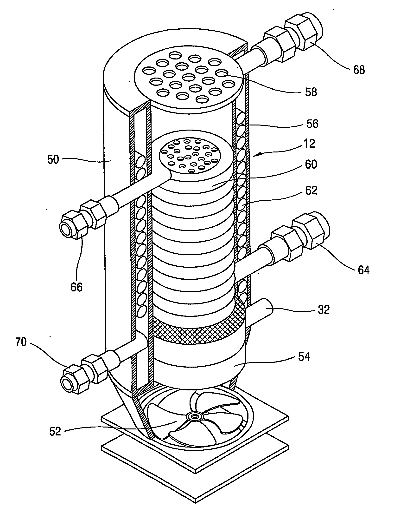
[0081]FIG. 11 is a sectional view showing a heating unit of the fuel cell system according to the present invention.

[0082] The heating unit according to the third embodiment is composed of a thermoelectric module 250 installed at the fuel supplying line 14 and the fuel recycling line 28 for heating fuel supplied to the fuel cell stack 6 from the fuel tank 8 and cooling fuel recycled into the fuel tank 8 from the fuel cell stack 6.

[0083] At the fuel supplying line 14, a heating container 252 for heating passing fuel supplied to the fuel cell stack 6 by a heat emitting operation of the thermoelectric module 250 is installed, and at the fuel recycling line 28, a cooling container 254 for cooling passing fuel recycled into the fuel tank 8 by a heat absorbing operation of the thermoelectric module 250 is installed.

[0084] Also, a fuel filter 256 for removing NaBO2 crystallized by passing through the cooling container 254 is installed at the fuel recycling line 28 between the cooling con...

first embodiment

[0085] The reaction aforementioned in the first embodiment is consecutively performed in the fuel cell stack 6, and a reaction such as 2H2O+NaBH4->NaBO2+4H2 is simultaneously performed in the anode 2.

[0086] The NaBO2 exhausted from the fuel cell stack 6 is dissolved in a constant high temperature and crystallized in a constant low temperature thus to block the fuel recycling line 28 or the fuel supplying line 14. To prevent this, a heat absorbing operation of the thermoelectric module 250 is used in order to remove the NaBO2 before it is recycled into the fuel tank 8.

[0087] That is, when fuel exhausted from the fuel cell stack 6 is cooled by using a heat absorbing operation of the thermoelectric module 250, NaBO2 is crystallized and the crystallized BO2− is filtered by the fuel filter 256.

[0088] The thermoelectric module 250 uses the Peltier effect and comprises: a high temperature ceramic board 258 attached to the heating container 252; a low temperature ceramic board 260 attache...


PUM

PropertyMeasurementUnit
temperatureaaaaaaaaaa

Abstract

A fuel cell system comprising: a fuel cell stack (6) including an anode (2), a cathode (4), and an electrolyte membrane disposed therebetween; a fuel supplying unit connected with the anode of the fuel cell stack (6) by a fuel supplying line (14) for supplying hydrogen-including fuel to the anode (2); an air supplying unit (10) connected with the cathode of the fuel cell stack by an air supplying line (48) for supplying oxygen-including air to the cathode of the fuel cell stack; and a heating unit (12) for heating fuel supplied to the fuel cell stack into a proper temperature. According to this, a power source for driving the heating unit (12) is not required thus to enhance a performance of a fuel cell.

Description

TECHNICAL FIELD [0001] The present invention relates to a fuel cell system, and more particularly, to a fuel cell system capable of enhancing a performance of a fuel cell by accelerating a reaction speed of a fuel cell. BACKGROUND ART [0002] In general, a fuel cell system has been proposed as a substitution of fossil fuel and differently from a general cell (a second cell), it supplies fuel (hydrogen or hydrocarbon) to an anode and supplies oxygen to a cathode. Thus, the fuel cell system undergoes an electrochemical reaction between hydrogen and oxygen without a combustion reaction (oxidation reaction) of fuel and thereby directly converts an energy difference between before and after a reaction into electric energy. [0003] As shown in FIG. 1, a fuel cell system in accordance with the conventional art comprises: a fuel cell stack 106 that an anode 102 and a cathode 104 are stacked with plural numbers in a state that an electrolyte membrane (not shown) is disposed therebetween in ord...

Claims


Application Information

Patent Timeline
Patent Type & Authority Applications(United States)
IPC IPC(8): H01M8/04H01M8/02H01M8/06
CPCH01M8/04022Y02E60/50H01M8/0687H01M8/04097
Inventor CHO, TAE-HEEPARK, MYUNG-SEOKCHOI, HONGLEE, MYEONG-HOKIM, KYU-JUNGKIM, CHEOL-HWANHWANG, YONG-JUNKO, SEUNG-TAEHEO, SEONG-GEUN
Owner LG ELECTRONICS INC
Why Eureka
Try Eureka