Eureka AIR delivers breakthrough ideas for toughest innovation challenges, trusted by R&D personnel around the world.

Liquid Fuel Container, Fuel Cell System, and Portable Information Terminal Device

a technology of information terminal device and liquid fuel container, which is applied in the direction of cell components, cell component details, electrochemical generators, etc., can solve the problems of inconvenient handling of liquid fuel, low leakage risk, and consideration of safety, so as to reduce the risk of leakage, detect leakage, and be convenient to handle

Inactive Publication Date: 2008-01-31
PANASONIC CORP
View PDF17 Cites 13 Cited by
  • Summary
  • Abstract
  • Description
  • Claims
  • Application Information

AI Technical Summary

Benefits of technology

[0010]Particularly, in the case of DMFC, methanol (or a methanol aqueous solution) used for the fuel is colorless, and the liquid fuel is inconspicuous even when it leaks from the cartridge that holds the liquid fuel. Therefore, it is possible that the discovery of the leakage might be late. Moreover, when the fuel cell is employed as a power source for portable information equipment, the leakage of the liquid fuel to the outside might cause troubles of a short circuit in the main body or the peripherals of the equipment equipped with the fuel cell and the deterioration, contact failure and so on of electrical components. Furthermore, when methanol of a high concentration becomes used as a fuel as a consequence of an improvement in the fuel cell performance, the detection of fuel leakage becomes important also in terms of safety.
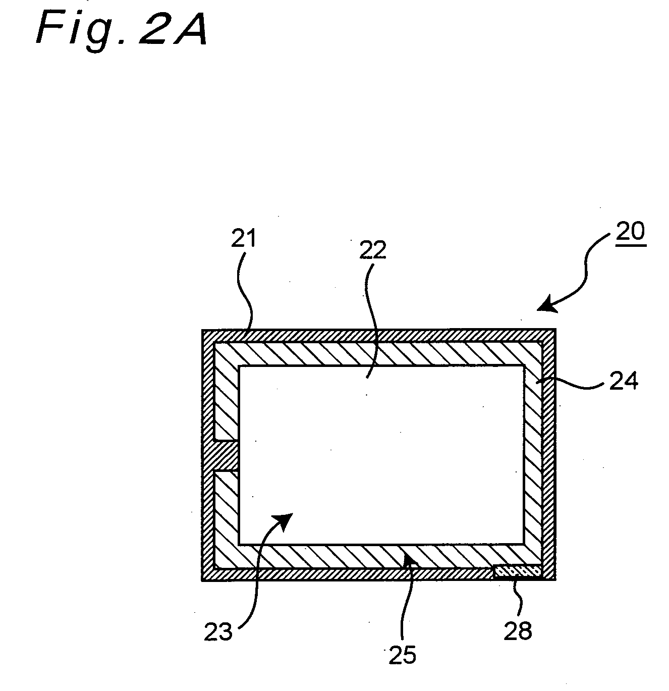
[0053]Moreover, by providing the coloring agent holding section with the absorber that absorbs and retains the liquid fuel leaked from the liquid fuel holding section, the risk of the leakage of the leaked liquid fuel to the outside of the container can be reduced, and the liquid fuel can be retained by the absorber in the state in which the liquid fuel is colored by the coloring agent. Therefore, by visually recognizing the change in the color of the absorber, the occurrence of the leakage can be visually recognized.

Problems solved by technology

There is no consideration for safety in the case where the cartridge is damaged by an impact or the like and the internal liquid fuel and the emission matters leak to the outside of the cartridge at the worst by informing the user of the leakage or other measures.
Particularly, in the case of DMFC, methanol (or a methanol aqueous solution) used for the fuel is colorless, and the liquid fuel is inconspicuous even when it leaks from the cartridge that holds the liquid fuel.
Therefore, it is possible that the discovery of the leakage might be late.
Moreover, when the fuel cell is employed as a power source for portable information equipment, the leakage of the liquid fuel to the outside might cause troubles of a short circuit in the main body or the peripherals of the equipment equipped with the fuel cell and the deterioration, contact failure and so on of electrical components.

Method used


Image

  • Liquid Fuel Container, Fuel Cell System, and Portable Information Terminal Device
  • Liquid Fuel Container, Fuel Cell System, and Portable Information Terminal Device
  • Liquid Fuel Container, Fuel Cell System, and Portable Information Terminal Device

Examples


first embodiment

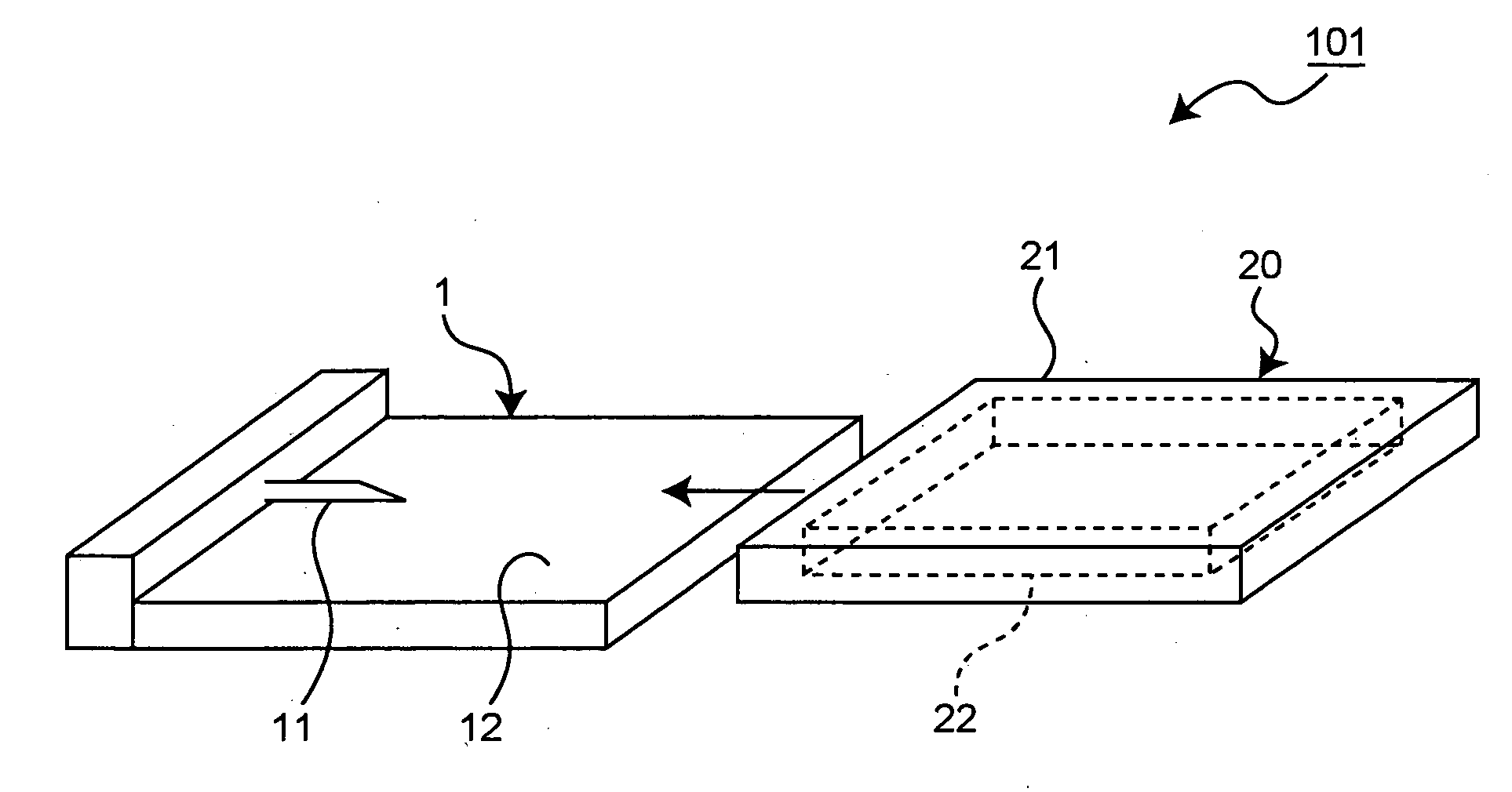
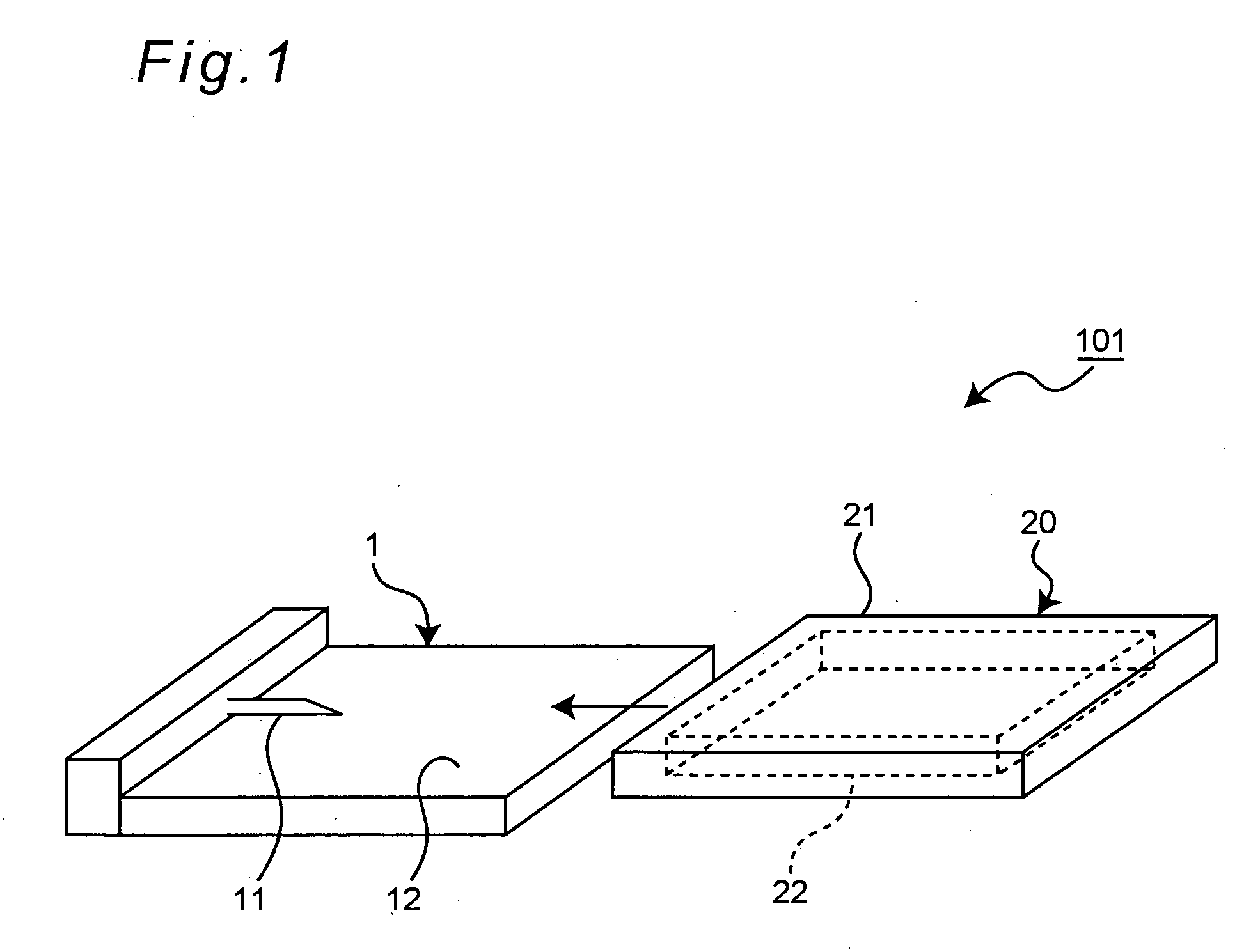
[0070]FIG. 1 shows a schematic perspective view showing the construction of a fuel cell system detachably equipped with a liquid fuel container according to the first embodiment of the present invention.

[0071]As shown in FIG. 1, a fuel cell system 101 has a power generation module 1 of one example of the fuel cell body for generating electric power by electrochemically converting the chemical energy of the supplied liquid fuel into electrical energy and a cartridge 20 of a liquid fuel of one example of the liquid fuel container for holding the liquid fuel in the power generation module 1 while allowing the fuel to be supplied. Moreover, the power generation module 1 has a cartridge mounting portion 12 (one example of the container mounting portion) on the illustrated upper surface of which the cartridge 20 is detachably mounted. The cartridge mounting portion 12 has an inlet 11 (one example of the connection port) of the liquid fuel from the equipped cartridge 20 into the power gene...

second embodiment

[0095]The present invention is not limited to the first embodiment but practicable in various modes. For example, FIG. 4 shows a schematic sectional view showing the internal structure of a cartridge 70 of one example of the liquid fuel container according to the second embodiment of the present invention. The cartridge 70 of the present second embodiment can also be used in the fuel cell system 101 of the first embodiment, and no description is provided for the components similar to those of the first embodiment.

[0096]As shown in FIG. 4, in the cartridge 70, a cobalt chloride paper 26 is placed in a coloring agent holding section 24 that is a space between the outer peripheral portion of the liquid fuel holding section 22 and the casing 21 instead of the powdered cobalt chloride 25.

[0097]The cobalt chloride paper 26 used here improves its waterproof property with the outside thereof provided with a laminate of polyethylene. Polyethylene is a safe material that is used for laminate ...

third embodiment

[0099]Next, FIG. 5 shows a schematic perspective view showing the construction of a fuel cell system 111 detachably equipped with a cartridge 80 of one example of the liquid fuel container according to the third embodiment of the present invention. FIG. 6 shows a schematic sectional view showing the internal construction of the cartridge 80.

[0100]The fuel cell system 111 of the present third embodiment differs from the fuel cell system 101 of the first embodiment in that it has a construction in which water (or emission matter) due to electric power generation is collected in the cartridge 80. In concrete, as shown in FIG. 5, a power generation module 91 provided for the fuel cell system 111 has a water outlet 92 besides the liquid fuel inlet 11. Further, the cartridge 80 has a product holding section 86, which can be attached to and detached from the power generation module 91, placed adjacent to the liquid fuel holding section 82 as shown in FIG. 6, releasably connected to the wat...


PUM

PropertyMeasurementUnit
coloraaaaaaaaaa
electric poweraaaaaaaaaa
poweraaaaaaaaaa

Abstract

By providing a coloring agent, which is brought in contact with the liquid fuel leaked from an outer peripheral portion of the liquid fuel holding section that is configured to hold the liquid fuel and by which the contact portion is changed in color, in at least part of the outer peripheral portion, the leakage of the liquid fuel from the liquid fuel holding section can be visually detected swiftly and easily without providing any special detection device.

Description

TECHNICAL FIELD[0001]The present invention relates to a liquid fuel container, a fuel cell system and a portable information terminal device capable of allowing the visual detection of the leakage of a liquid fuel.BACKGROUND ART[0002]A fuel cell system (hereinafter referred to as a fuel cell), which has a high conversion efficiency in electrochemically converting the chemical energy owned by the liquid fuel into electrical energy, attracts attention as effective energy supplying means (i.e., power generation method and device) from the viewpoint of energy saving and environmental protection. Furthermore, such a fuel cell system, which can continuously generate an electric power while the liquid fuel continues being supplied, attracts attention as a power source for use in portable information equipment such as laptop personal computers of which the power consumption keeps increasing in accordance with remarkable functional advancement and as a transportable power source. Moreover, t...

Claims


Application Information

Patent Timeline
Patent Type & Authority Applications(United States)
IPC IPC(8): H01M2/02H01M8/00H01M8/04H01M8/10
CPCH01M8/04208Y02E60/50Y02B90/18H01M2250/30Y02B90/10
Inventor IYODA, MAKOTOINOUE, HIROTONAKAO, SUGURUIWATA, YUKIHIROYOKOTA, YASUOTAKASU, TOSHIAKI
Owner PANASONIC CORP
Why Eureka
Eureka Blog
Learn More