Connector for attaching an alignment rod to a bone structure
a technology of connecting rods and bones, applied in the field of spinal alignment systems, can solve the problems of system failure, loss of desired spine position, and failure of the hook and rod system, and achieve the effect of minimizing the adverse effects
- Summary
- Abstract
- Description
- Claims
- Application Information
AI Technical Summary
Benefits of technology
Problems solved by technology
Method used
Image
Examples
second embodiment
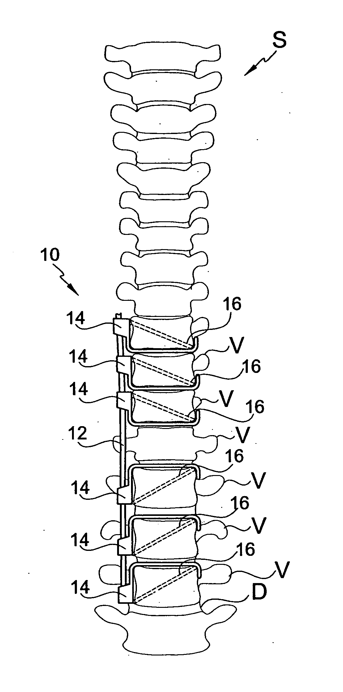
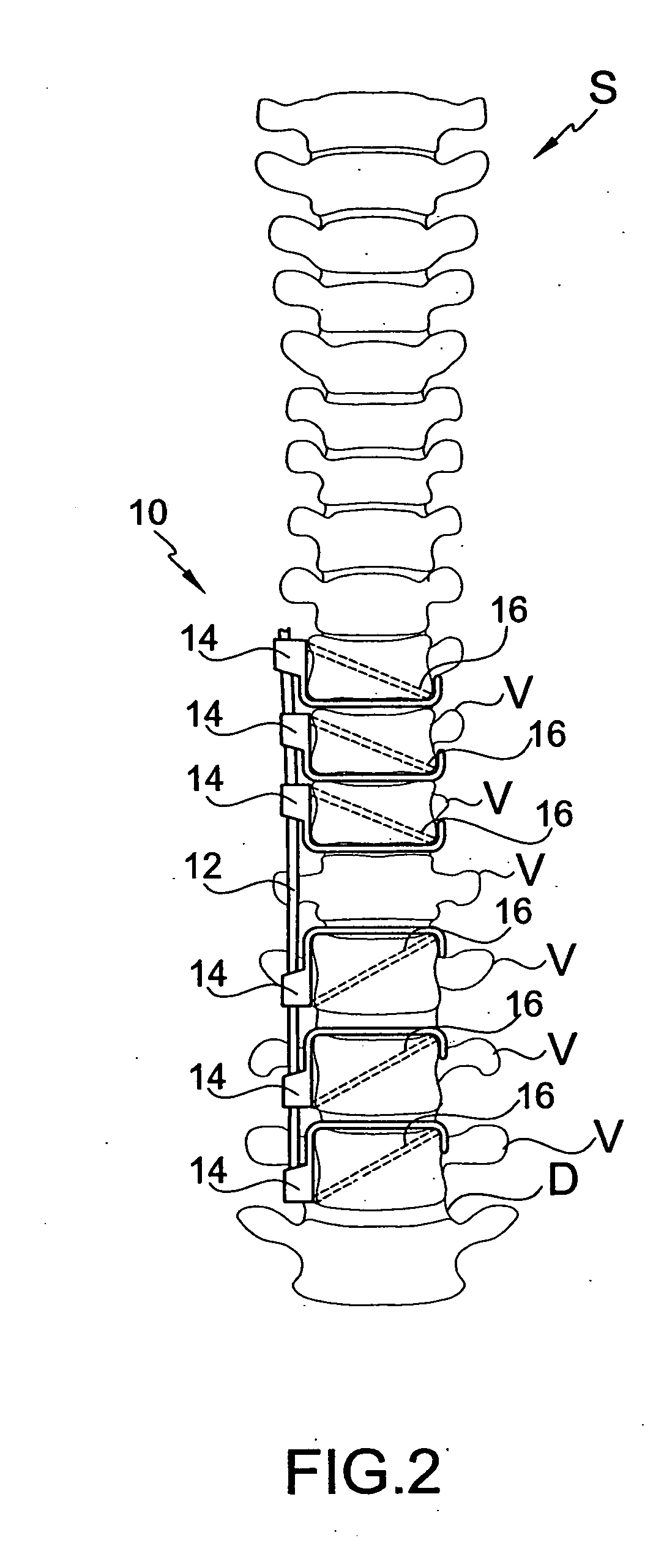
[0063] As discussed above, the bone fastener 16 can be disposed at any angle and can pass through different parts of connector 14. Examples of alternative embodiments in this regard are now described with reference to FIGS. 6A-6F. In FIG. 6A, a connector 114 includes a base 118 and a first portion 132 of a hook 120 extending from the base 118 adjacent the second open end 144 of a channel 122 formed in the base 118. A guide aperture 128 extends through the channel 122 adjacent the second open end 144 of the channel 122. A second hook portion 134 extends from the first hook portion 132 and is longer as compared to the second hook portion 34 of the connector 14, as illustrated in FIGS. 2-5. A threaded bore 130 is located adjacent the free end of second hook portion 134 of the hook 120.
third embodiment
[0064]FIG. 6B illustrates the connector 214 including a base 218 and a first portion 232 of a hook 220 extending from the base 218 adjacent the second open end 244 of a channel 222 formed in the base 218. A second hook portion 234 extends from the first hook portion 232 and is longer as compared to the second hook portion 34 of the connector 14, as illustrated in FIGS. 2-5. The connector 214 includes a guide aperture 228 extending through the channel 222 adjacent the first open end 242 of the channel 222 and a threaded bore 230 adjacent the free end of the second hook portion 234 of the hook 220. The bone fastener 16 is inserted through the guide aperture 228 and threaded into the threaded bore 230.
[0065]FIG. 6C illustrates a fourth embodiment of the connector 314. Like the first embodiment of FIGS. 2-5, the connector 314 includes a base 318 and a first portion 332 of a hook 320 extending from the base 318 adjacent the second open end 344 of a channel 322 formed in the base 318. A g...
fifth embodiment
[0066]FIG. 6D illustrates the connector 414. The connector 414 includes a base 418 and a first portion 432 of a hook 420 extending from the base 418 adjacent the second open end 444 of a channel 422 formed in the base 418. A guide aperture 454 extends through the first hook portion 432. A second hook portion 434 extends from the first hook portion 432 and is lengthened compared to the second hook portion 34 of the connector 14, as illustrated in FIGS. 2-5. A threaded bore 430 is located adjacent the free end of the second hook portion 432 of the hook 420. The bone fastener 16 is inserted through the guide aperture 454 and threaded into the threaded bore 430.
PUM
 Abstract
Description
Claims
Application Information
 - R&D
- Intellectual Property
- Life Sciences
- Materials
- Tech Scout
- Unparalleled Data Quality
- Higher Quality Content
- 60% Fewer Hallucinations
Browse by: Latest US Patents, China's latest patents, Technical Efficacy Thesaurus, Application Domain, Technology Topic, Popular Technical Reports.
© 2025 PatSnap. All rights reserved.Legal|Privacy policy|Modern Slavery Act Transparency Statement|Sitemap|About US| Contact US: help@patsnap.com


