Diversity receiver device

a receiver device and diversity technology, applied in the field of diversity receiver devices, can solve the problems of large circuit complexity of receivers, insufficient diversity gain, and inability to converge to optimal values, so as to reduce delay spread

Inactive Publication Date: 2006-12-28
KK TOSHIBA
View PDF6 Cites 31 Cited by
  • Summary
  • Abstract
  • Description
  • Claims
  • Application Information

AI Technical Summary

Benefits of technology

[0016] According to an aspect of the present invention, there is provided a diversity receiver device comprising N antennas to receive orthogonal frequency-division signals; N digital filters to filter the signals received by the N antennas in order to reduce a delay spread of each of the signals received by the N antennas to obtain filtered signals; K (K≦N) beamforming units configured to subject the filtered signals to a beam combining process by using combining weights; a decomposition unit configured to subject the filtered signals to eigen-decomposition to generate N eigenvalues; a weight setting unit configured to select K eigenvalues in descending order from the generated N eigenvalues in order to set eigenvectors corresponding to the K eigenvalues to the beamforming units as the combing weight, respectively; K fast Fourier transformation (FFT) units configured to subject output signals of the beamforming units to fast Fourier transformation to obtain FFT signals; and a diversity combining unit configured to combine the FFT signals to generate a modulated signal.

Problems solved by technology

Regarding a pre-FFT combining diversity disclosed by Matsuoka et al., in a multipath propagation model with delay spread, since the result of combining performed by a signal space possessed by an eigenvector does not necessarily maximize the signal to noise ratio (SNR), a diversity gain may not be obtained sufficiently.
Accordingly, if the number of samples of the training signal is small, averaging may not be performed sufficiently, meaning that the diversity weight will not be converged to an optimal value.
Therefore, in a wireless communication system where thousands of subcarriers are used, such as the digital terrestrial broadcasting, a circuit complexity of a receiver becomes massive.

Method used


Image

  • Diversity receiver device
  • Diversity receiver device
  • Diversity receiver device

Examples


second embodiment

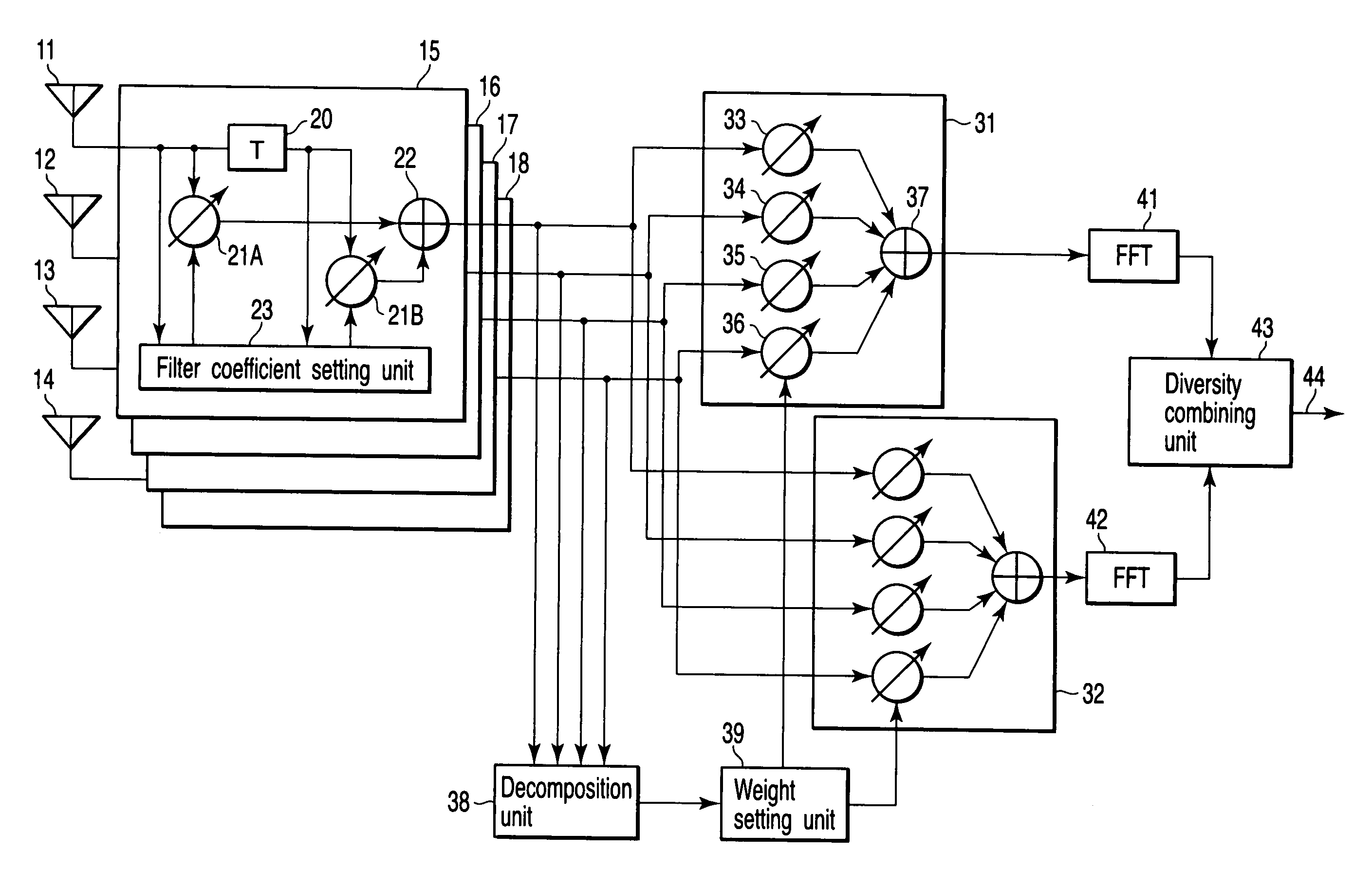
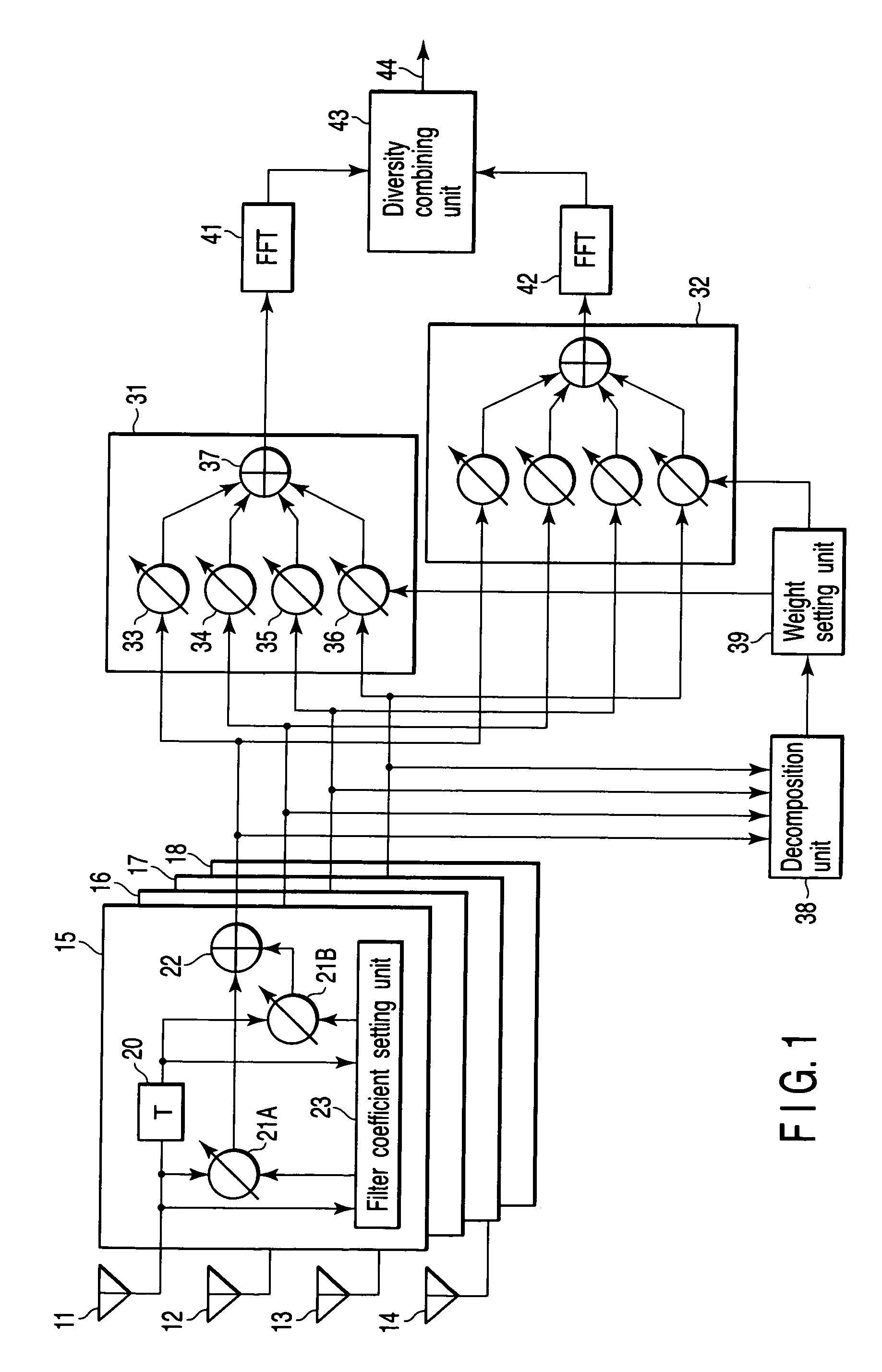
[0052]FIG. 8 is a diversity receiver device according to the second embodiment of the present invention, which differs from FIG. 1 in that it is equipped with M pieces (M>2) of beamforming units 31 to 3M. That is to say, output signals from digital filters 15 to 18 are input to beamforming units 31 to 3M. The beamforming units 31 to 3M each have multipliers 33 to 36 and an adder 37 likewise the beamforming units 31 and 32 in FIG. 1.

[0053] A weight setting unit 39 determines eigenvectors corresponding to eigenvalues λ1 to λ4 (λ1>λ2>λ3>λ4), which is determined by an eigenvalue decomposition unit 38, and sets an eigenvector corresponding to the maximum eigenvalue λ1 for the first beamforming unit 31 as a combining weight. Further, the weight setting unit 39 sets an eigenvector corresponding to the second largest eigenvalue λ2 for the beamforming unit 32 as a combining weight. Similarly, hereafter, an eigenvector corresponding to a Jth largest eigenvalue λJ is set for the Jth beamformi...


PUM


Abstract

A diversity receiver device includes N antennas to receive OFDM signals, N digital filters to filter the signals received by the N antennas in order to reduce delay spread, K (K≦N) beamforming units configured to subject the filtered signals to a beamforming process by using combining weights, an eigen-decomposition unit configured to subject the filtered signals to eigen-decomposition to generate N eigenvalues, a weight setting unit configured to select K eigenvalues in descending order from the generated N eigenvalues in order to set eigenvectors corresponding to the K eigenvalues to the beamforming units as the combing weight, respectively, K FFT units configured to subject the output signals of the beamforming units to fast Fourier transformation to output FFT signals, and a diversity combining unit configured to combine the FFT signals.

Description

CROSS-REFERENCE TO RELATED APPLICATIONS [0001] This application is based upon and claims the benefit of priority from prior Japanese Patent Application No. 2005-185369, filed Jun. 24, 2005, the entire contents of which are incorporated herein by reference. BACKGROUND OF THE INVENTION [0002] 1. Field of the Invention [0003] The present invention relates to a diversity receiver device used in a wireless communication system employing orthogonal frequency-division multiplexing (OFDM). [0004] 2. Description of the Related Art [0005] Digital terrestrial television broadcasting in Japan has adopted OFDM as its modulation method in order to increase transmission rates and realize robustness against a delayed interference. In OFDM, data is allocated to orthogonal subcarriers on the frequency axis to perform modulation. At a transmitting side of an OFDM wireless communication system, an inverse fast Fourier transform (IFFT) process is performed in order to transform a frequency domain signal...

Claims


Application Information

Patent Timeline
Patent Type & Authority Applications(United States)
IPC IPC(8): G06F17/10
CPCH04B7/0845H04L27/2647H04L25/0204H04B7/0848
Inventor MATSUOKA, HIDEHIROKASAMI, HIDEOTSURUTA, MAKOTOMURAKAMI, YASUSHI
Owner KK TOSHIBA
Why Eureka
Try Eureka