
Heat curing device and method of fabricating liquid crystal display device using the same

Inactive Publication Date: 2007-01-04
LG DISPLAY CO LTD
View PDF5 Cites 2 Cited by
  • Summary
  • Abstract
  • Description
  • Claims
  • Application Information

AI Technical Summary

Benefits of technology

[0020] An advantage of the present invention is to provide a heat curing device for curing a sealant, in which sagging of a substrate is avoided without causing damage to an active region of a liquid crystal cell.
[0021] Another advantage of the present invention is to provide a heat curing device for curing a sealant that uses reduced process time when changing the size of a liquid crystal cell.
[0022] Another advantage of the present invention is to provide a method of fabricating an LCD device using the heat curing device for curing a sealant.

Problems solved by technology

In the liquid crystal injection method, a relatively long time is required for injecting liquid crystal, particularly when forming large sized LCD cells.
However, because of difficulties in achieving a complete cure of the sealant using UV rays, a heat curing process may be carried out along with the UV curing process.

Method used


Image

  • Heat curing device and method of fabricating liquid crystal display device using the same
  • Heat curing device and method of fabricating liquid crystal display device using the same
  • Heat curing device and method of fabricating liquid crystal display device using the same

Examples


first embodiment

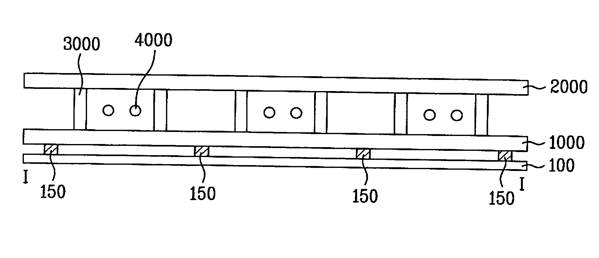
[0046] As shown in FIG. 4, the heat curing device according to the present invention includes a set of multi-staged supports 100, protrusion structures 150 formed on each support 100, a plurality of toothed wheels or gears 200 respectively connected with the multi-staged supports 100, a belt 300 connected with the gears 200, and a grip 400 connected with at least one of the gears 200.

[0047] The supports 100 are positioned in a chamber to support the substrate. The supports 100 are arranged in multiple stages with supports of each multi-stage arranged between the lower portion and the upper portion of the chamber. The ends of each support 100 are respectively supported by a first mechanism 170a and a second mechanism 170b. Although the supports 100 are illustrated as having rectangular shaped sections in the drawings, the sections may have other shapes such as a polygonal shape.

[0048] At least two sets of supports 100 may be arranged horizontally in a row to support a substrate. In ...

fourth embodiment

[0060]FIG. 7 is a perspective view illustrating a heat curing device according to the present invention. The heat curing device shown in FIG. 7 employs links 500 and a link bar 600 to rotate the multi-staged supports 100 simultaneously.

[0061] As shown in FIG. 7, the heat curing device according to the fourth embodiment of the present invention includes multi-staged supports 100, protrusion structures 150 formed on each support 100, a plurality of links 500 respectively connected with the multi-staged supports 100, a link bar 600 connected with the links 500, and a grip 400 connected with at least one of the links 500.

[0062] Since the supports 100 and the protrusion structures 150 are identical to those of the first embodiment, their description will be omitted.

[0063] The links 500 are connected with the supports 100 and to a link bar 600. At least one of the links 500 is connected to the grip 400.

[0064] When the grip 400 is rotated, a link 500 connected to the grip 400 is also ro...

fifth embodiment

[0067]FIG. 8 is a perspective view illustrating a heat curing device according to the present invention. Unlike the heat curing device shown in FIG. 4 in which the supports are rotated by rotation of the grip, the heat curing device shown in FIG. 8 is structured to automatically rotate all the supports using rotation supplied by a motor.

[0068] The detailed description of elements of the heat curing device according to the fifth embodiment of the present invention that are the same as those of the heat curing device according to the first embodiment of the present invention will be omitted.

[0069] In the heat curing device according to the fifth embodiment of the present invention, a belt 300 is rotated by a motor 700, and each of the gears 200 is rotated by rotation of the belt 300. In addition, each of the supports 100 is rotated by rotation of a respective gear 200. As a result, all the supports 100 are rotated using rotation supplied by the motor 700.

[0070] When a support 100 is...


PUM


Abstract

A heat curing device includes supports positioned in a chamber to support a substrate, the supports having sections, and protrusion structures formed on the sections of the supports to contact a dummy area of the substrate, wherein the supports may be rotated with respect to a horizontal axis. The sections of the supports may have a polygonal structure with the protrusion structures are formed on the polygonal sections of the supports, so that a plurality of protrusion structure patterns can be formed on one support. Since the supports are rotatable, the protrusion structure patterns supporting a substrate may be readily changed.

Description

[0001] This application claims the benefit of Korean Patent Application No. P2005-0058274, filed on Jun. 30, 2005, which is hereby incorporated by reference for all purposes as if fully set forth herein. BACKGROUND OF THE INVENTION [0002] 1. Field of the Invention [0003] The present invention relates to a liquid crystal display (LCD) device, and more particularly, to a heat curing device for curing a sealant. [0004] 2. Discussion of the Related Art [0005] Among ultra-slim flat panel displays having a display screen whose thickness is merely several centimeters, a liquid crystal display device (LCD) has the advantage of a low operation voltage, resulting in low power consumption, and portability. Accordingly, the LCD can be widely used in a variety of applications, such as notebook computers, monitors, spacecraft and aircraft instrumentation. [0006] Hereinafter, a related art LCD. device will be described. [0007] As shown in FIG. 1, the related art LCD device includes a lower substra...

Claims


Application Information

Patent Timeline
IPC IPC(8): G02F1/1339
CPCG02F1/1339G02F1/1303G02F1/13
Inventor RYU, JAE CHOONPARK, CHUN OKSHIN, JAE HO
Owner LG DISPLAY CO LTD
Features
  • Generate Ideas
  • Intellectual Property
  • Life Sciences
  • Materials
  • Tech Scout
  • Unparalleled Data Quality
  • Higher Quality Content
  • 60% Fewer Hallucinations
Learn More