
Power supply system for random pulse load and control method thereof

A power supply system, random pulse technology, applied in the AC network to reduce harmonics/ripple, reactive power compensation, harmonic reduction devices, etc. Reduce network voltage and frequency fluctuations, reduce current or voltage fluctuations, and meet steady-state and dynamic requirements

Inactive Publication Date: 2019-01-15
CSR ZHUZHOU ELECTRIC LOCOMOTIVE RES INST
View PDF3 Cites 3 Cited by
  • Summary
  • Abstract
  • Description
  • Claims
  • Application Information

AI Technical Summary

Problems solved by technology

However, the pulsating power of random pulse-type loads will cause severe fluctuations in the intermediate DC bus voltage, which will affect the normal operation of important loads, reduce the service life of equipment, and fail to meet the steady-state and dynamic requirements of the system. Power fluctuations and shocks lead to power quality problems such as grid voltage drops, sags, or grid connection failures, and affect the stability of the front-end power supply system and the performance and life of generators, etc.

Method used


Image

  • Power supply system for random pulse load and control method thereof
  • Power supply system for random pulse load and control method thereof

Examples


Embodiment 1

[0037] In order to solve the above-mentioned technical problems existing in the prior art, an embodiment of the present invention provides a power supply system for random pulse loads.

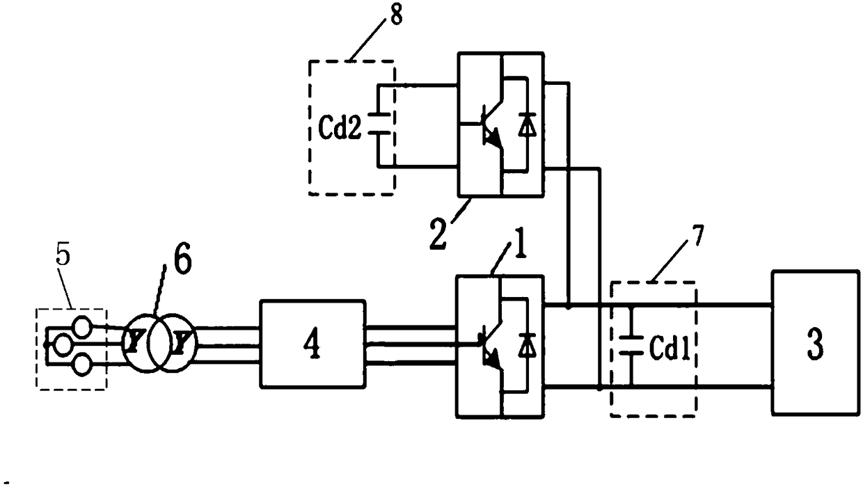
[0038] figure 1 A schematic circuit diagram of a power supply system for a random pulse load according to an embodiment of the present invention is shown. refer to figure 1 , the power supply system for random pulse loads includes a fully-controlled converter 1 , a fully-controlled power converter 2 , a first energy storage unit 7 and a second energy storage unit 8 .

[0039] The output end of the fully-controlled converter 1 is connected between the power grid 5 and the random pulse load 3, and is used to convert the AC power transmitted from the power grid 5 side into a direct current that meets the requirements, that is, to provide the random pulse load 3 with the required The average steady-state power component of power. Wherein, the average steady-state power component represents the ...

Embodiment 2

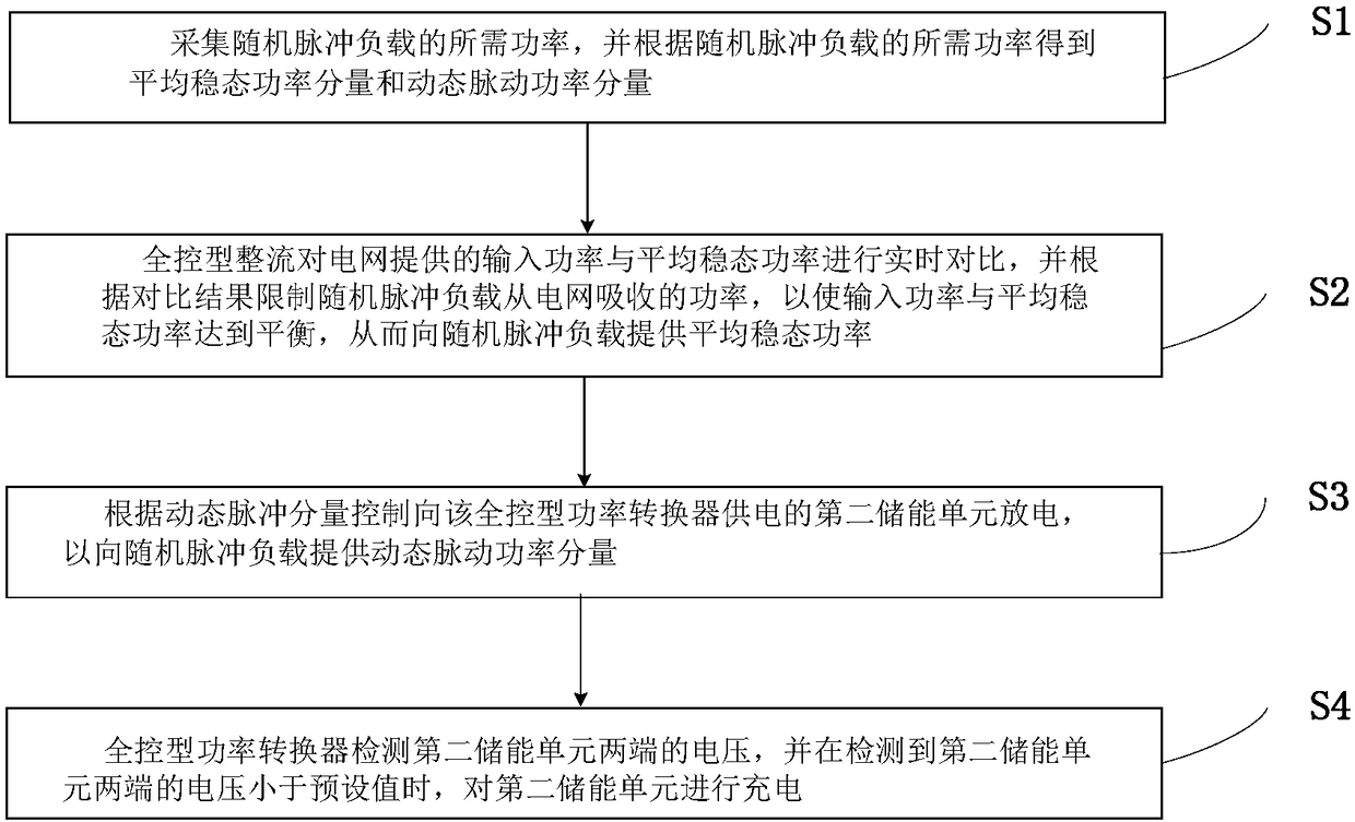
[0048] Correspondingly, the present invention also provides a control method of the power supply system for random pulse loads in Embodiment 1, figure 2 A schematic diagram of the steps of the method for controlling the power supply system for random pulse loads according to Embodiment 1 of the present invention is shown.

[0049] refer to figure 2 , The control method of the power supply system for random pulse loads includes a collection step S1, a first control step S2, a second control step S3 and a charging detection step S4.

[0050] In the collection step S1 : collect the required power of the random pulse load 3 , and obtain the average steady-state power component and dynamic pulsating power component according to the required power of the random pulse load 3 .

[0051] Specifically, the control unit of the fully-controlled converter 1 collects the current I of the random pulse load 3 and the voltage Ud1 across Cd1, and calculates the real-time power required by th...


PUM


Abstract

The invention discloses a power supply system of random pulse load and a control method thereof. The power supply system for random pulse load includes a fully controlled converter, a fully controlledpower converter and a second energy storage unit. The output of the fully controlled converter is connected to the DC bus to provide the average steady-state power component of the required power tothe load. The output of the fully controlled power converter is connected to a dc bus for supplying a dynamic pulsating power component of the required power to the load. A second energy storage unitis used for supplying power to the fully controlled power converter. A method for supply power by parallel connection of a full-control convert and a full-control power converter, It reduces the amplitude of voltage and frequency fluctuation, avoids the power quality problems such as voltage sag, sag or grid-connected failure, improves the power quality of grid side, prolongs the service life of equipment, and realizes the long-term continuous and stable operation of the system.

Description

technical field [0001] The invention relates to the technical field of power supplies, in particular to a random pulse load power supply system and a control method thereof. Background technique [0002] The power required by random pulsed loads (such as radar, ocean waves, tides, etc.) is generally pulsating power, which is generally connected to a large power grid, and the pulsating power is withstand through a large-capacity and strong power grid. However, connecting random pulse loads to the large power grid will cause certain fluctuations in the frequency and amplitude of the power grid. However, if a random pulse load is connected to a weak power grid, there will be severe power fluctuations, and long-term operation will affect the stability of the power supply system. [0003] The random pulse load usually adopts the DC power supply system, and the traditional power supply scheme is based on the diode uncontrolled rectification method to provide DC power. However, t...

Claims


Application Information

Patent Timeline
Patent Type & Authority Applications(China)
IPC IPC(8): H02J3/24H02J3/18H02J3/01
CPCH02J3/01H02J3/18H02J3/24Y02E40/30Y02E40/40
Inventor 罗文广苏亮亮孙璐黄超吴奕付如愿
Owner CSR ZHUZHOU ELECTRIC LOCOMOTIVE RES INST
Features
  • Generate Ideas
  • Intellectual Property
  • Life Sciences
  • Materials
  • Tech Scout
  • Unparalleled Data Quality
  • Higher Quality Content
  • 60% Fewer Hallucinations
Learn More