Flat display apparatus
a technology for display apparatuses and flat panels, applied in the direction of identification means, instruments, cooling/ventilation/heating modifications, etc., can solve the problems of reducing reducing the weight, and compromising the support function of the chassis base, so as to reduce the number of processing steps, reduce the weight, and reduce the noise
- Summary
- Abstract
- Description
- Claims
- Application Information
AI Technical Summary
Benefits of technology
Problems solved by technology
Method used
Image

Examples
first embodiment
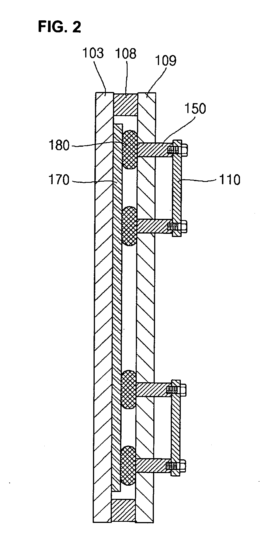
[0036]FIG. 2 illustrates a cross-sectional view of a flat display apparatus according to the present invention.
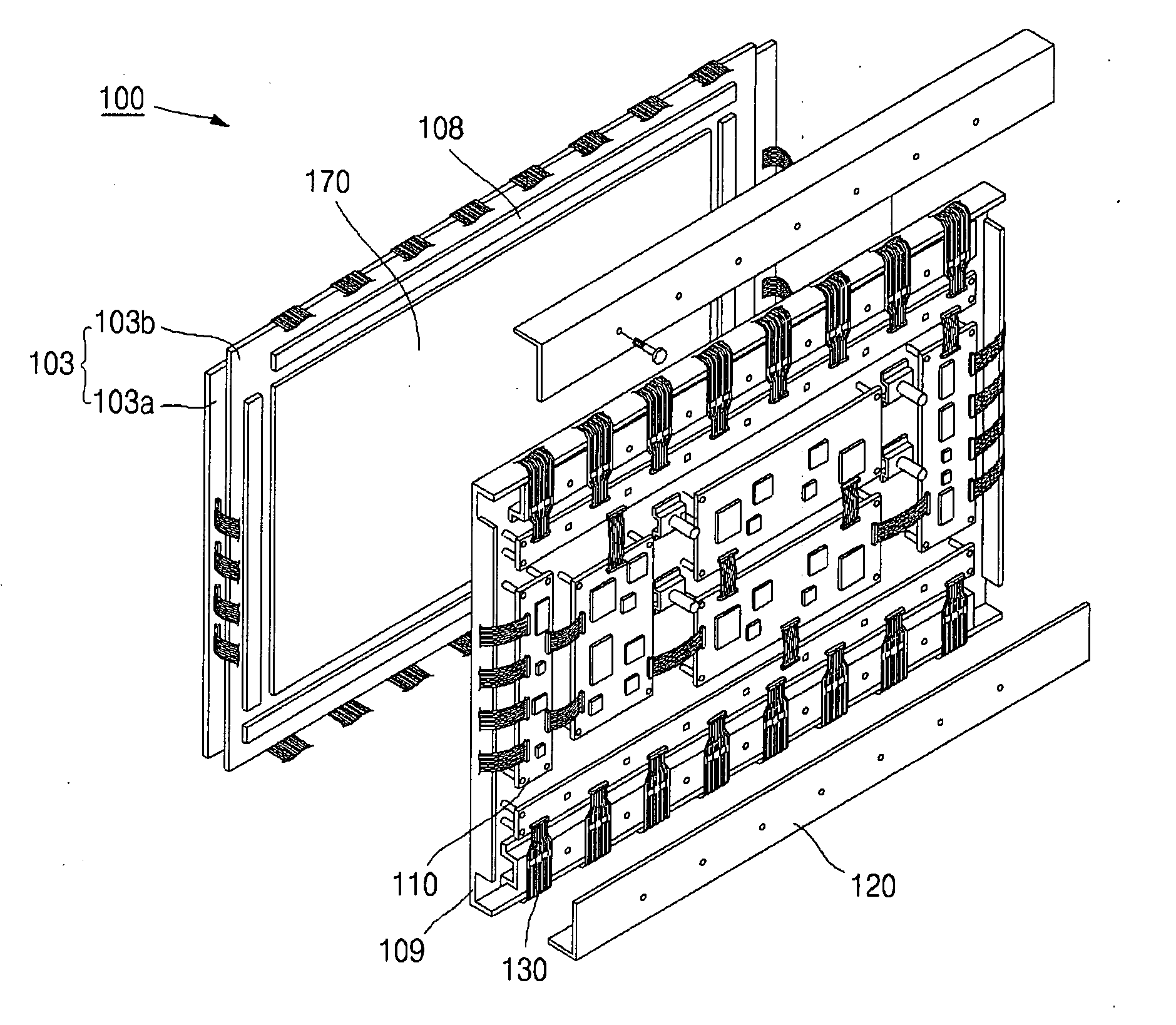
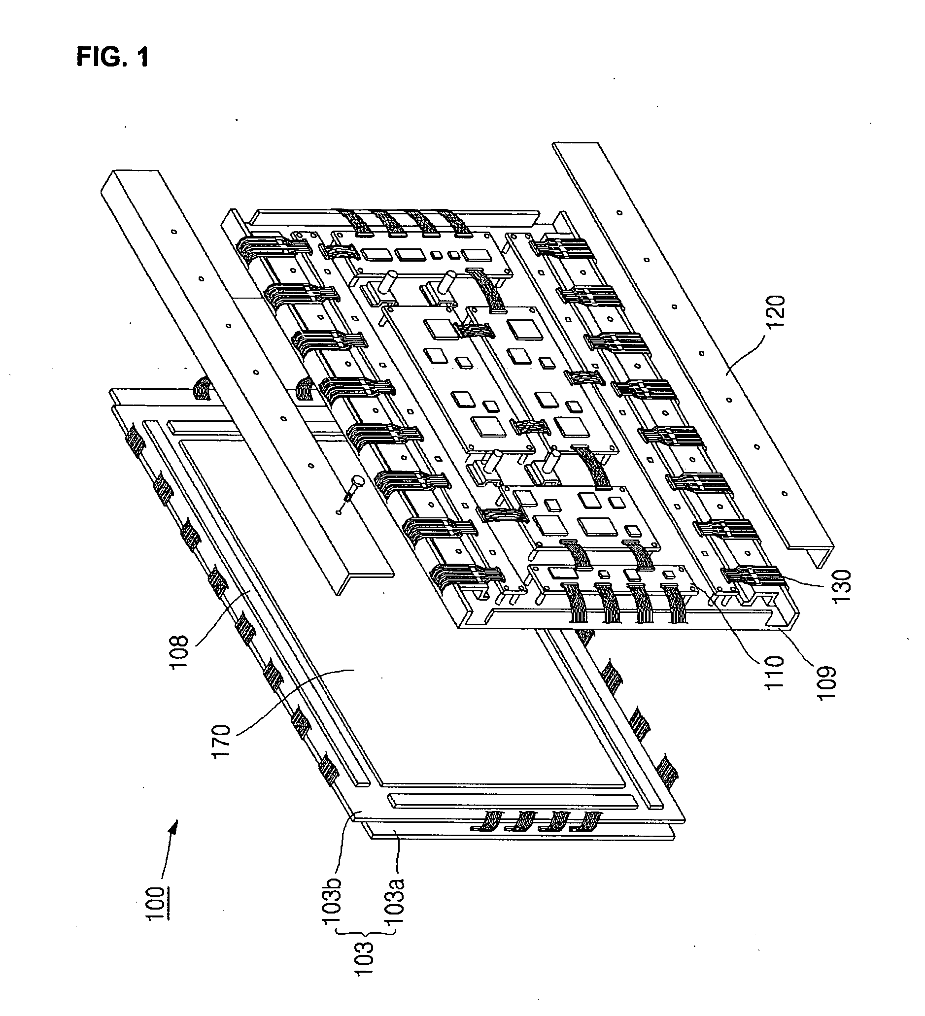
[0037] In the flat display apparatus according to the first embodiment of the present invention, referring to FIG. 2, the panel 103 may have the conductive sheet 170 attached to a back surface thereof and may be fixed by the adhesive members 108 to the chassis base 109. The circuit portion 110 may be supported by the bosses 150 fixedly coupled to the chassis base 109.
[0038] An insulating material used for the chassis base 109 may include a synthetic resin, e.g., a polyester resin, an epoxy resin or a polycarbonate resin. The polyester resin may be reinforced with fiberglass and may be referred to as fiber reinforced plastic (FRP). Fiber reinforced plastics (FRPs) may have steel-like-strength and may be made using a recently developed molding method. The polycarbonate resin may be transparent, have excellent mechanical character, be non-toxic, have good heat resistance and ...
second embodiment
[0048]FIG. 3 illustrates a cross-sectional view of a flat display apparatus according to the present invention.
[0049] Referring to FIG. 3, the flat display apparatus, according to the second embodiment of the present invention, may include the panel 103, the conductive sheet 170 attached to the back surface of the panel 103, the chassis base 109 attached by the adhesive member 108 to the panel 103, and the circuit portion 110, which may be supported by bosses 150 fixed to the chassis base 109. The conductive member 182 may be between the conductive sheet 170 and the chassis base 109. The conductive member 182 may have one side electrically connected to the conductive sheet 170 and the other side electrically connected to the first end of each boss 150.
[0050] Hereinafter, the description of elements which are the same as those of the above-mentioned first embodiment of the present invention will be omitted.
[0051] The conductive member 182 of the flat display apparatus according to ...
third embodiment
[0053]FIG. 4 illustrates a cross-sectional view of a flat display apparatus according to the present invention.
[0054] Referring to FIG. 4, the flat display apparatus, according to the third embodiment of the present invention, may include the panel 103, the conductive sheet 170 attached to the back surface of the panel 103, the chassis base 109 attached by the adhesive member 108 to the panel 103, and the circuit portion 110 supported by bosses 150 fixed to the chassis base 109.
[0055] Hereinafter, the description of elements which are the same as those in the above-mentioned embodiment of the present invention will be omitted.
[0056] Conductive coupling members 160 may be used to fix the bosses 150 to the chassis base 109. Each conductive coupling member 160 may be coupled at a first end to the first end of each boss 150, so that conductive coupling members 160 can be electrically connected to the bosses 150. If the bosses 150 are conductive, there is no problem in the electrical c...
PUM
 Abstract
Description
Claims
Application Information
 - R&D
- Intellectual Property
- Life Sciences
- Materials
- Tech Scout
- Unparalleled Data Quality
- Higher Quality Content
- 60% Fewer Hallucinations
Browse by: Latest US Patents, China's latest patents, Technical Efficacy Thesaurus, Application Domain, Technology Topic, Popular Technical Reports.
© 2025 PatSnap. All rights reserved.Legal|Privacy policy|Modern Slavery Act Transparency Statement|Sitemap|About US| Contact US: help@patsnap.com