Backlight unit and method for controlling temperature thereof

a backlight unit and temperature control technology, applied in the field of backlight units, can solve the problems of reducing the lifespan of lamps, increasing the possibility of lamp failure, and unsuitable appliances requiring a light and compact display, and achieve the effect of effectively controlling the heat absorption operation and enhancing the initial brightness

Inactive Publication Date: 2007-01-04
LG DISPLAY CO LTD
View PDF0 Cites 3 Cited by
  • Summary
  • Abstract
  • Description
  • Claims
  • Application Information

AI Technical Summary

Benefits of technology

[0024] An advantage of the present invention is to provide a backlight unit that can effectively control a heat absorption operation required during a high temperature condition and a heat absorption operation required during a low temperature condition, thereby solving problems associated with lamp performance and lamp lifespan, and achieving an enhanced initial brightness effect.
[0025] Additional advantages, objects, and features of the invention will be set forth in part in the description which follows and in part will become apparent to those having ordinary skill in the art upon examination of the following or may be learned from practice of the invention. The objectives and other advantages of the invention may be realized and attained by the structure particularly pointed out in the written description and claims hereof as well as the appended drawings. To achieve these objects and other advantages and in accordance with the purpose of the invention, as embodied and broadly described herein, a backlight unit includes: a cover bottom including a first portion, a second portion spaced apart from the first portion, and a third portion connecting the first and second portions; a lamp arranged at the first portion of the cover bottom; and a current direction controller that is connected to the first and second portions and that controls a direction of current supplied to the cover bottom according to a Thompson's coefficient of the cover bottom.
[0026] In another aspect of the present invention, in a method for controlling a temperature of a backlight unit including: a cover bottom including a first portion, a second portion spaced apart from the first portion, and a third portion connecting the first and second portions; a lamp arranged at the first portion of the cover bottom; and a current direction controller that is connected to the first and second portions and that controls a direction of current supplied to the cover bottom according to a Thompson's coefficient of the cover bottom, the method includes controlling the direction of the current such that the current flows in the cover bottom from a lower temperature side to a higher temperature side or from the higher temperature side or the lower temperature side, using the current direction controller in accordance with whether the Thompson's coefficient of the cover bottom is positive (+) or negative (−), when a temperature gradient is generated in the cover bottom.
[0027] It is to be understood that both the foregoing general description and the following detailed description of the present invention are exemplary and explanatory and are intended to provide further explanation of the invention as claimed.

Problems solved by technology

However, such CRTs have a heavy and bulky structure that makes them unsuitable for appliances requiring a light and compact display.
The larger number and greater operating time of the lamps in the direct type backlight arrangement results in an increased possibility of lamp failure and in a reduced lifespan of the lamps.
Increased temperatures of the lamp 1 and of the light incidence region accompany the overheating of the lamp from continuous driving of the lamp and result in a degradation of the performance of the lamp a reduction in the lifespan of the lamp.

Method used


Image

  • Backlight unit and method for controlling temperature thereof
  • Backlight unit and method for controlling temperature thereof
  • Backlight unit and method for controlling temperature thereof

Examples


first embodiment

[0045] First, the backlight unit according to the present invention will be described.

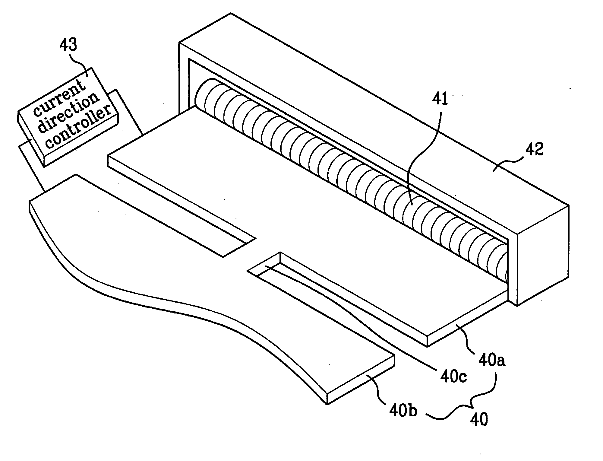
[0046] As shown in FIG. 4, the backlight unit according to the first embodiment of the present invention includes a cover bottom 40 that is divided into first, second, and third portions 40a, 40b, and 40c forming a closed loop, a lamp 41 that is arranged at one side or either side of the cover bottom 40, and has a straight structure, and a lamp housing 42 that encloses the lamp 41, except for a light emission face of the lamp 41. The first portion 40a may have a straight shape. The lamp 41 is arranged at an edge of the first portion 40a that is spaced apart from the second portion 40b. The lamp 41 may be a CCFL or may include LEDs. The backlight unit also includes a current direction controller 43 that is connected between the first and second portions 40a and 40b, to control the supply of current and the supply direction of the current.

[0047] The backlight unit according to the first embodiment o...

second embodiment

[0052] Now, a backlight unit according to the present invention will be described.

[0053] As shown in FIG. 5, the backlight unit according to the second embodiment of the present invention includes a cover bottom 50 that is divided into first, second, and third portions 50a, 50b, and 50c forming a closed loop; a lamp 51 that extends along two edges of the first portion 50a of the cover bottom 50, and has an L-shaped structure; and a lamp housing that encloses the lamp 51, except for a light emission face of the lamp 51. The first portion 50a may have an L shaped structure. The lamp may be a CCFL or may include LEDs. The backlight unit also includes a current direction controller 54 that is connected between the first and second portions 50a and 50b, to control the supply of current and the supply direction of the current.

[0054] The backlight unit according to the second embodiment of the present invention, in addition to the above-described configuration, includes a light guide plat...

third embodiment

[0058] Next, a backlight unit according to the present invention will be described.

[0059] As shown in FIG. 6, the backlight unit according to the third embodiment of the present invention includes: a cover bottom 60 that is divided into first, second, and third portions 60a, 60b, and 60c forming a closed loop; a lamp 61 that extends along three edges of the first portion 60a of the cover bottom 60, and has a U-shaped structure; and a lamp housing that encloses the lamp 61, except for a light emission face of the lamp 61. The first portion 60a may have a U shaped structure. The backlight unit also includes a current direction controller 64 that is connected between the first and second portions 60a and 60b, to control the supply of current and the supply direction of the current. The lamp 61 may be a CCFL or may include LEDs.

[0060] The backlight unit according to the third embodiment of the present invention, in addition to the above-described configuration, includes a light guide p...


PUM


Abstract

A backlight unit for effectively controlling a heat absorption operation required under a high temperature condition and a heat emission operation required under a low temperature condition to increase lamp performance and lamp lifespan, and achieve an enhanced initial brightness increase effect includes: a cover bottom including a first portion, a second portion spaced apart from the first portion, and a third portion connecting the first and second portions; a lamp arranged at the first portion of the cover bottom; and a current direction controller connected to the first and second portions and adapted to control a direction of current supplied to the cover bottom according to a Thompson's coefficient of the cover bottom. A method for controlling a temperature of a backlight unit includes controlling the direction of current supplied to the cover bottom according to a Thompson's coefficient of the cover bottom to emit or absorb heat.

Description

[0001] This application claims the benefit of Korean Patent Application No. P2005-0058618, filed on Jun. 30, 2005, which is hereby incorporated by reference as if fully set forth herein. BACKGROUND OF THE INVENTION [0002] 1. Field of the Invention [0003] The present invention relates to a backlight unit, and more particularly, to a backlight unit that uses the Thompson effect to achieve an enhanced heat discharge efficiency and an enhanced heating efficiency. [0004] 2. Discussion of the Related Art [0005] Cathode ray tubes (CRT) have been generally used as the display systems for equipment such as televisions, monitors of metering devices, and data terminal equipment. However, such CRTs have a heavy and bulky structure that makes them unsuitable for appliances requiring a light and compact display. [0006] Various alternative display devices have been developed to substitute for the CRT as displays when the size and weight limitations of CRT based displays do not provide the compactn...

Claims


Application Information

Patent Timeline
Patent Type & Authority Applications(United States)
IPC IPC(8): F21V7/04
CPCH05B41/39G02F2001/133628G02F1/133628G02F1/1335
Inventor SUNG, MOON CHULLEE, KYU TAE
Owner LG DISPLAY CO LTD
Why Eureka
Try Eureka