Image correction across multiple spectral regimes

a technology of spectral regime and image, applied in scene recognition, instruments, computing, etc., can solve the problems of system distorted, image distorted generally, and optical limitations of instruments

Inactive Publication Date: 2007-01-04
TELEDYNE FLIR LLC
View PDF4 Cites 70 Cited by
  • Summary
  • Abstract
  • Description
  • Claims
  • Application Information

AI Technical Summary

Benefits of technology

[0005] The present teachings provide systems, including apparatus and methods, for obtaining and / or correcting images, particularly from atmospheric and / or other distortions. These corrections may involve, among others, determining corrective information in a first (e.g., visible) wavelength regime, and then applying the corrective information in a second (e.g., longer) wavelength regime, such as infrared (IR) or millimeter-wave (MMW) wavelengths, in real time or with post-processing. For example, these corrections may include scaling a phase diversity correction from one wavelength to another. These systems may be useful in any suitable imaging context, including navigation, targeting, search and rescue, law enforcement, and / or surveillance, among others.

Problems solved by technology

Unfortunately, when an optical system obtains images based on image data that have passed through a medium, the images obtained generally will be distorted both by the medium, and by the components of the optical system itself.
For example, the image of an object viewed with a telescope or other long-range imaging system may be distorted both by atmospheric effects (e.g., the scintillation, convection, turbulence, scatter, and varying index of refraction of the atmosphere, among others, which can induce various spatial and temporal perturbations in the incoming wavefront, etc.), and by mechanical, thermal, and optical limitations of the instrument (e.g., path-length error introduced by out-of-focus components of the field of view, limitations on the collection of spatial frequencies imposed by the objective aperture, uncorrected aberration in the objective lens, mirror deformations generated by supporting devices, etc.).
These distortions occur, for example, when ground-based telescopes (or other imaging instruments) obtain images of objects on the ground, in the air, or in space, and when airborne or space-based telescopes (or other imaging instruments) in aircraft or on satellites obtain images of objects within Earth's atmosphere, such as objects on or near Earth's surface.
The effects of atmospheric distortion can significantly limit image resolution.
For example, atmospheric distortion can limit the best “seeing conditions” to approximately 1 microradian at high-altitude astronomical observatories, looking straight up.
The limiting resolution becomes rapidly worse for lower-altitude and near-horizontal viewing scenarios typical for cameras and electro-optical systems.
However, this may be prohibitively expensive—or otherwise impractical—as a technique to correct relatively long-wavelength images, statically or in real time, due in part to the difficulty and expense of rapidly collecting and processing image data in such regimes, including the additional hardware complexity needed for the infrared.

Method used


Image

  • Image correction across multiple spectral regimes
  • Image correction across multiple spectral regimes
  • Image correction across multiple spectral regimes

Examples


example 1

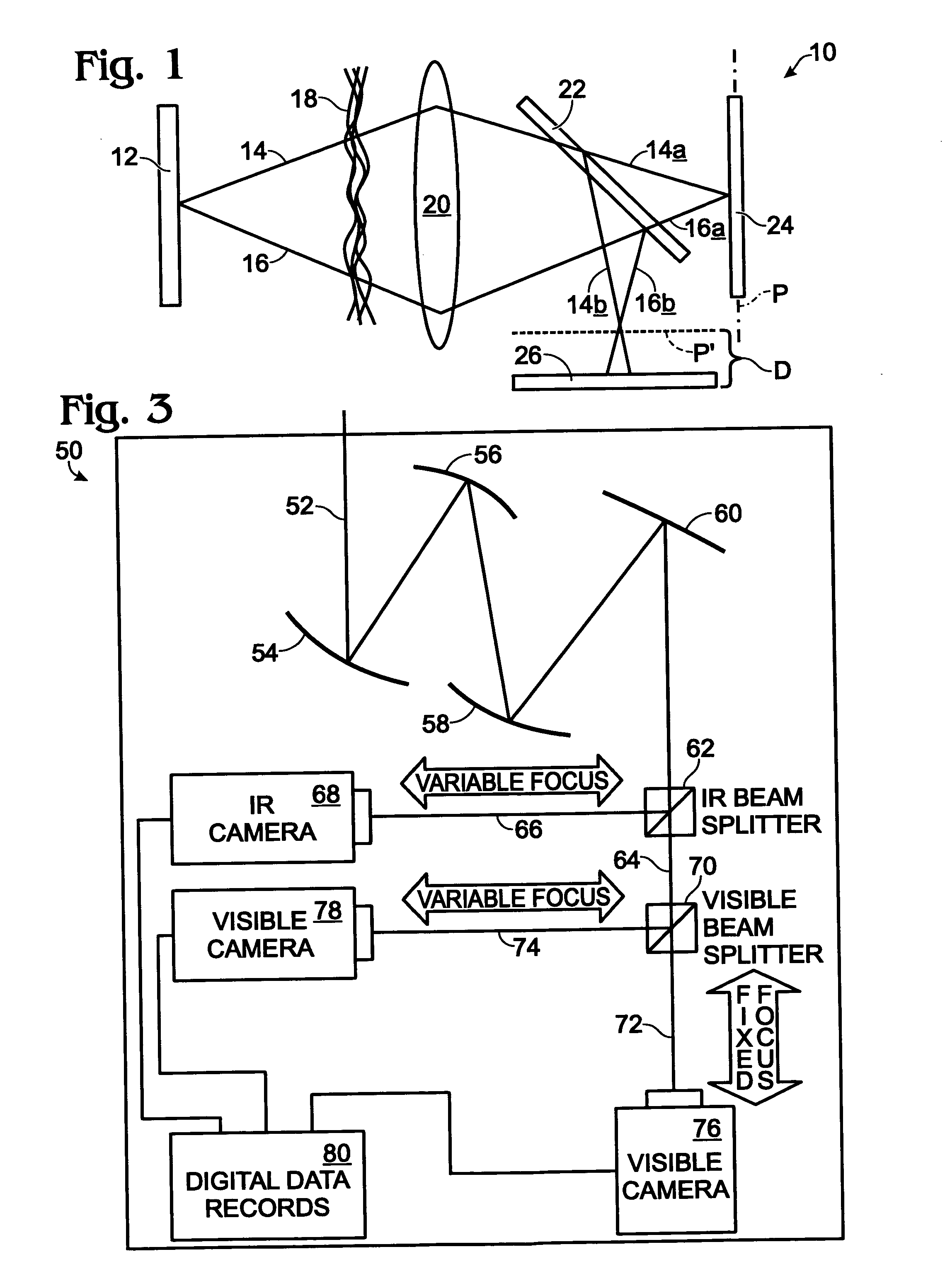
[0041] This section describes an example of some of the techniques described above; see FIG. 3.

[0042]FIG. 3 is a schematic diagram showing an optical system, generally indicated at 50, for using visible image data to correct an infrared image using phase diversity methods. In this example, an incoming image signal 52 arrives at the optical system, and may encounter various optical components including lenses and mirrors, such as mirrors 54, 56, 58, 60. These optical components may be used, for example, to focus, magnify, and / or redirect the incoming signal.

[0043] Signal 52 then arrives at a beamsplitter 62, which divides or splits the signal into two beams 64, 66. Beamsplitters, such as beamsplitter 62, generally comprise optical devices configured to separate electromagnetic radiation into different wavelength bands, for example, separating a visible light band from an infrared radiation band. Suitable beamsplitters (such as dichroic or multi-dichroic beamsplitters) may operate b...

example 2

[0048] This section describes additional techniques that optionally may be used with, or in lieu of, techniques described elsewhere herein for improving image acquisition and / or quality. See, e.g., U.S. Provisional Patent Application Ser. No. 60 / 696,306, filed Jul. 1, 2005, which is incorporated herein by reference in its entirety for all purposes.

[0049] Kolmogorov developed mathematical constructs for estimating atmospheric effects. In these constructs, the resolution limits imposed by the atmosphere vary with path length (to the 8 / 5th power), altitude (to the − 4 / 3 power), and sensing wavelength (to the ⅕th power). The temporal effects from the atmosphere also vary approximately with wavelength. Thus, based on these constructs, it is possible to measure the phase diversity and calculate a correction for the wavefront for longer wavelengths. Tilt of the wavefront usually is the dominant wavefront error and can be corrected merely by tilting a flat mirror, for example, as described...

example 3

[0052] This section provides an example of an image correction system, according to aspects of the present teachings, being used in an aircraft to correct infrared, millimeter-wave, and / or visible imagery in real time; see FIG. 4.

[0053]FIG. 4 shows a helicopter 100 equipped with an image correction system 102. Image correction system 102 may be substantially similar or identical to system 50, described above in Example 1 (and optionally augmented by Example 2) and depicted in FIG. 3, and may be configured to correct infrared, millimeter-wave, and / or visible imagery using visible regime phase diverse imagery. The corrected infrared or millimeter-wave imagery may be recorded and / or displayed on a heads-up display, generally indicated at 104 in FIG. 4. Thus, a pilot of helicopter 100 may use system 102 to view corrected infrared or millimeter-wave imagery in real time on display 104. In addition, system 102 may provide a second heads-up display (not shown) configured to display correc...


PUM


Abstract

Systems, including apparatus and methods, for obtaining and/or correcting images, particularly from atmospheric and/or other distortions. These corrections may involve, among others, determining corrective information in a first (e.g., visible) wavelength regime, and then applying the corrective information in a second (e.g., longer) wavelength regime, such as infrared (IR) or millimeter-wave (MMW) wavelengths, in real time or with post-processing. For example, these corrections may include scaling a phase diversity correction from one wavelength to another. These systems may be useful in any suitable imaging context, including navigation, targeting, search and rescue, law enforcement, and/or surveillance, among others.

Description

CROSS-REFERENCE TO RELATED APPLICATION [0001] This application is based upon and claims the benefit under 35 U.S.C. §119(e) of U.S. Provisional Patent Application Ser. No. 60 / 696,299, filed Jul. 1, 2005, which is incorporated herein by reference in its entirety for all purposes.INTRODUCTION [0002] Optical systems may be used to form and / or record images of objects and / or scenes. Unfortunately, when an optical system obtains images based on image data that have passed through a medium, the images obtained generally will be distorted both by the medium, and by the components of the optical system itself. For example, the image of an object viewed with a telescope or other long-range imaging system may be distorted both by atmospheric effects (e.g., the scintillation, convection, turbulence, scatter, and varying index of refraction of the atmosphere, among others, which can induce various spatial and temporal perturbations in the incoming wavefront, etc.), and by mechanical, thermal, a...

Claims


Application Information

Patent Timeline
Patent Type & Authority Applications(United States)
IPC IPC(8): G06K9/40G06K9/64G06V10/30G06V20/13
CPCG06K9/0063H04N5/332G06K9/40G06V20/13G06V10/30H04N23/11
Inventor MILLER, JOHN L.ARCHER, CYNTHIA ISEMANWORLEY, MILTON S.
Owner TELEDYNE FLIR LLC
Why Eureka
Try Eureka