Connector and a connector assembly method

a technology of connectors and assembly methods, applied in the direction of coupling contact members, coupling device connections, electrical devices, etc., can solve the problem of narrowing the application range of connectors, and achieve the effect of preventing forcible connection of auxiliary connectors, and reducing the number of parts

Inactive Publication Date: 2007-01-04
SUMITOMO WIRING SYST LTD
View PDF9 Cites 30 Cited by
  • Summary
  • Abstract
  • Description
  • Claims
  • Application Information

AI Technical Summary

Benefits of technology

[0009] A partition wall of a mating auxiliary connector preferably can slide into a clearance between facing surfaces of two auxiliary connectors that are adjacent to each other in the arranging direction. Thus, forcible connection of the auxiliary connectors can be prevented. Accordingly, there is no need for a special forcible-connection preventing construction, and the connector can be made even smaller.
[0010] At least one seal preferably is arranged at a rear part of the each auxiliary connector to seal around wires connected with terminal fittings. Additionally, a wall of the mating auxiliary connector may be brought hermetically into close contact with a peripheral portion of the seal. Accordingly, the seal provides sealing between the seal and the mating auxiliary connectors and also seals between the seal and the wires connected with the terminal fittings. Thus, the auxiliary connector does not need a plurality of kinds of seals, and the number of parts can be reduced.
[0011] At least one rear holder preferably is assembled at a rear part of the respective auxiliary connectors for retaining the seal. The auxiliary connectors are united in the arranging direction by the rear holder and are accommodated into the frame in a united state to define the positioning means. Thus, assembling efficiency is improved and a sealing performance of the seal is ensured.
[0012] Plural rear holders preferably are provided in one-to-one correspondence with the respective auxiliary connectors and can be coupled to each other substantially in the arranging direction. Thus, an operation of inserting the terminal fittings can be performed for each auxiliary connector. As a result, erroneously inserted the terminal fittings are unlikely and the wires are easier to handle, thereby improving assembling efficiency.
[0017] Each auxiliary connector preferably is formed with at least one guidable portion that can slide in contact with at least one guide of the frame when the auxiliary connector is mounted into the frame. The protection cap preferably has at least one mounting portion detachably engageable with the guidable portion before the auxiliary connectors are mounted into the frame. Thus, it is not necessary to provide the auxiliary connectors with a special construction for mounting the protection cap, and the constructions of the respective auxiliary connectors can be simplified.

Problems solved by technology

This may narrow the range of applications for the connector.

Method used


Image

  • Connector and a connector assembly method
  • Connector and a connector assembly method
  • Connector and a connector assembly method

Examples


Embodiment Construction

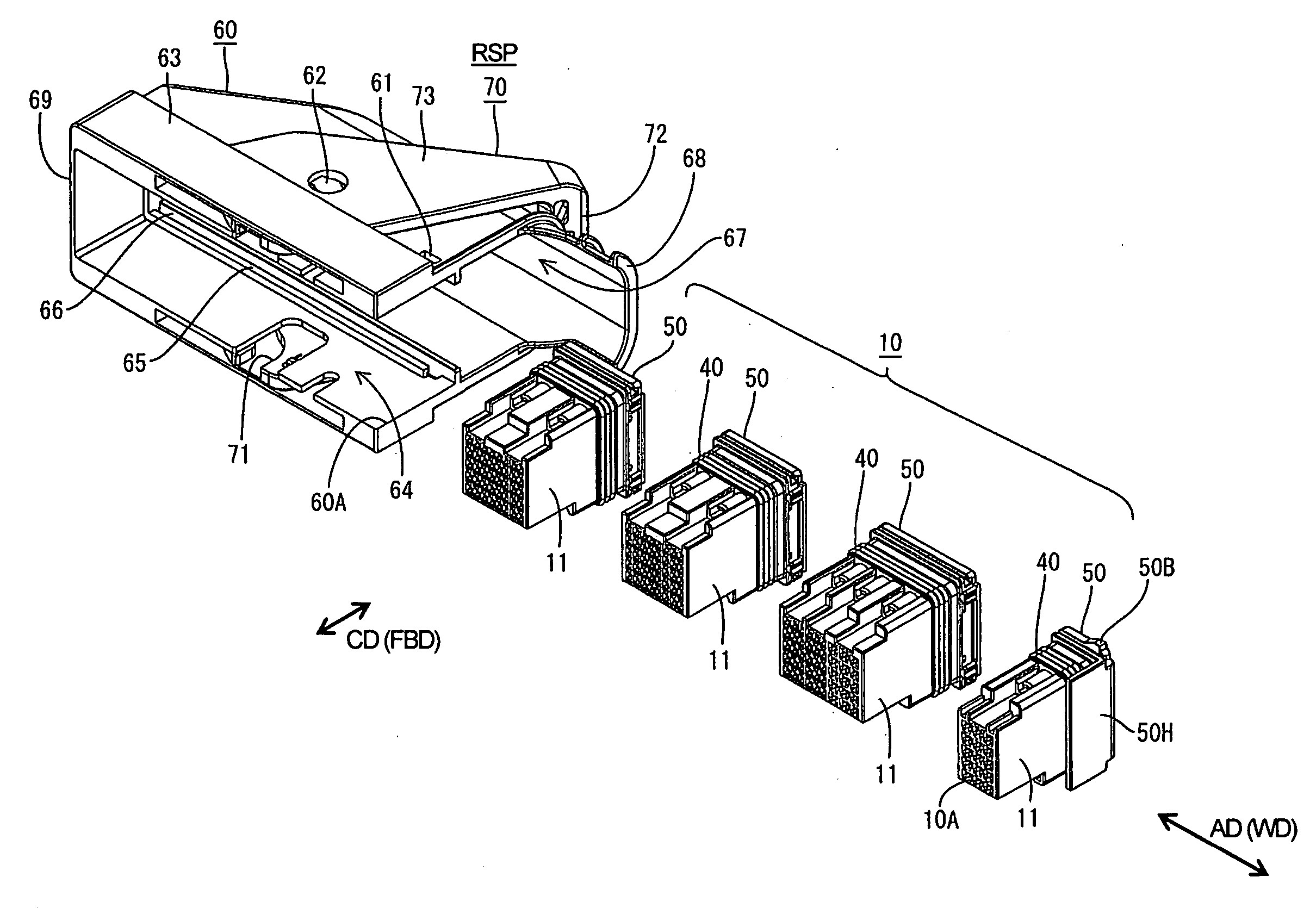
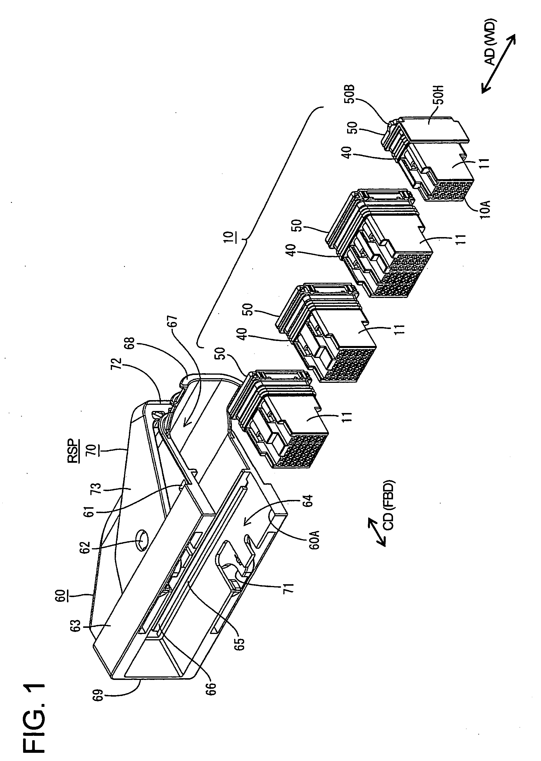
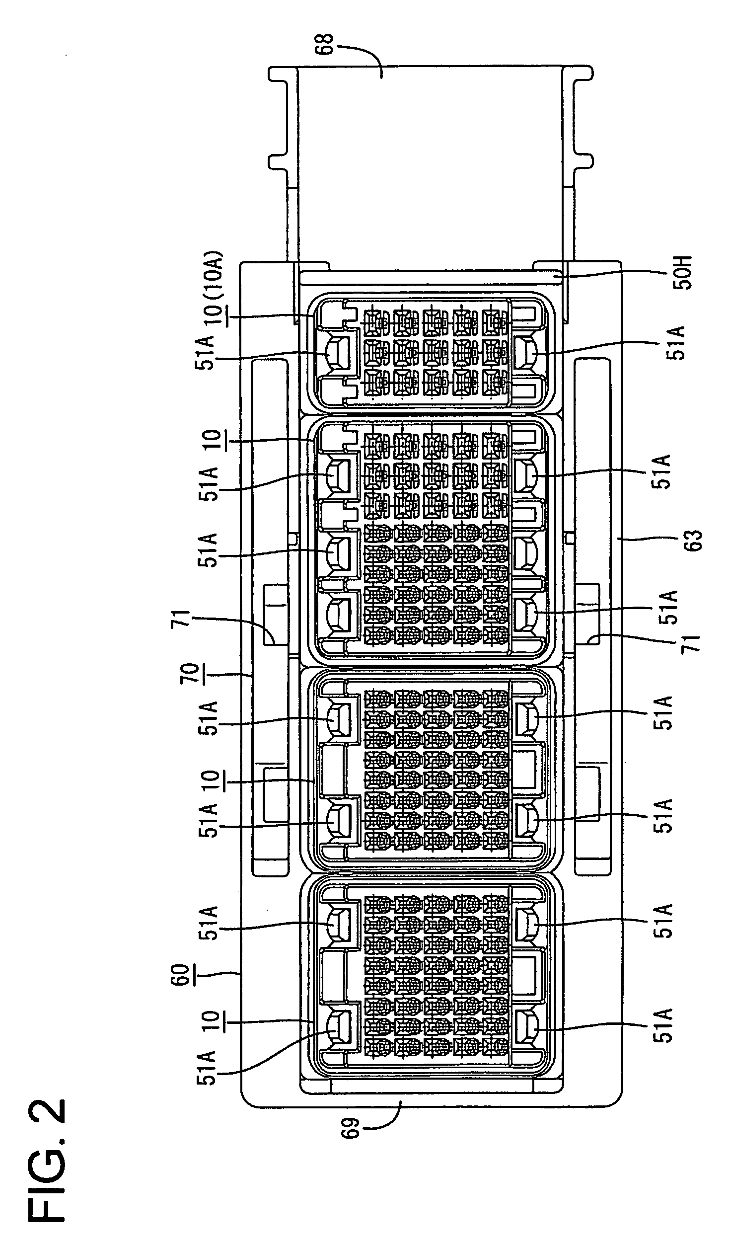
[0034] A connector assembly according to the invention is described with reference to FIGS. 1 to 13. The assembly includes a divided watertight female connector that is connectable with a mating male connector. The female connector includes auxiliary connectors 10 that are accommodated in a frame 60. An end of the female connector that is to be connected with the male connector is referred to as the front in the following description.

[0035] As shown in FIGS. 12 and 13, the mating male connector is intended for mounting on a printed circuit board, and has a plurality of differently dimensioned male auxiliary connectors 90 arranged substantially side by side in a width direction WD. The auxiliary connectors 90 are coupled to each other by a coupling plate 93 arranged on the rear surfaces of the auxiliary connectors 90, as shown in FIG. 12. Each auxiliary connector 90 has a rectangular tubular receptacle 91 with an open front end. The receptacles 91 adjacent to each other in the width...


PUM


Abstract

Each of a plurality of auxiliary connector (10) includes an auxiliary housing (11), a seal (40) attached to the rear of the auxiliary housing (11), and a rear holder (50) mounted on the rear of the seal (40) to retain the seal (40). Auxiliary connectors (10) that are adjacent in an arranging direction are united by the rear holders (50). The united auxiliary connectors (10) are inserted into a frame (60) in the arranging direction through an insertion opening (60A) of the frame (60), and are retained in the frame (60) by engaging a lock (50B) on the last auxiliary connector (10A) and an interlocking portion (61) of the frame (60). The frame (60) has no partition walls between the auxiliary connectors (10). Thus, the connector is narrowed by a total thickness of the partition walls.

Description

BACKGROUND OF THE INVENTION [0001] 1. Field of the Invention [0002] The invention relates to a connector and to a connector assembly method. [0003] 2. Description of the Related Art [0004] Japanese Unexamined Patent Publication No. 2000-150058 discloses a connector with a plurality of auxiliary connectors. Each auxiliary connector has cavities for accommodating terminal fittings. The respective auxiliary connectors are accommodated individually in accommodating chambers of a frame of the connector. A seal is mounted on the rear surface of each auxiliary connector to provide sealing around wires connected with the terminal fittings and a rear holder is mounted on the rear surface of the seal to retain the seal. [0005] The above-described divided connector is enlarged in an arranging or width direction of the auxiliary connectors. More particularly, the frame has partition walls for partitioning the accommodating chambers for the respective auxiliary connectors. The width of the frame...

Claims


Application Information

Patent Timeline
Patent Type & Authority Applications(United States)
IPC IPC(8): H01R13/60
CPCH01R13/508H01R13/514H01R13/518H01R13/4362H01R13/62938H01R9/2408H01R13/5221
Inventor TABATA, MASAAKITSUJI, TAKESHINAKATA, TAKEHIROKOBAYASHI, TOMOHIKOMORIKAWA, SATOSHI
Owner SUMITOMO WIRING SYST LTD
Why Eureka
Try Eureka