
Heart valve delivery system

a delivery system and heart valve technology, applied in balloon catheters, medical science, surgery, etc., can solve the problems of not being adapted, complicated and costly, and limited use of catheters, and achieve the effect of facilitating navigation

Active Publication Date: 2007-01-04
EDWARDS LIFESCIENCES CORP
View PDF99 Cites 946 Cited by
  • Summary
  • Abstract
  • Description
  • Claims
  • Application Information

AI Technical Summary

Benefits of technology

[0007] Preferred embodiments of the present invention provide a heart valve delivery system for delivery of a prosthetic (i.e., replacement) heart valve to a native valve site within the human vasculature. The delivery system includes a delivery sleeve assembly having a steerable section for facilitating navigation around bends. The system is well suited for advancing a prosthetic valve through the aorta (i.e., in a retrograde approach) for replacing a stenotic aortic valve.
[0014] In one variation, the prosthetic valve is pushed through stenotic leaflets of an aortic valve site while the steerable section is bent. In another variation, the balloon catheter is distally advanced relative to the delivery sleeve assembly until the prosthetic valve is located within the native valve site. The prosthetic valve preferably comprises a stent portion supporting a valve structure. Because the delivery sleeve assembly provides steerability, an outer surface of the stent may be substantially exposed during advancement over the aortic arch without damaging the aorta. For enhanced pushability, a distal end of the steerable section preferably abuts a proximal end of the stent portion while advancing the prosthetic valve to the native valve site.

Problems solved by technology

The usefulness of catheters is largely limited by the ability of the catheter to successfully navigate through small vessels and around tight bends, such as around the aortic arch.
The use of many connected segments, however, is complicated and costly.
However, known devices of this type are used as stylets and have not been adapted for use in a steerable catheter.
However, these bands add unnecessary complexity to the device and are therefore undesirable for many uses.
Although a variety of bendable and steerable devices have been proposed over the years, each of the existing devices has shortcomings that limit its effectiveness.

Method used


Image

  • Heart valve delivery system
  • Heart valve delivery system
  • Heart valve delivery system

Examples


Embodiment Construction

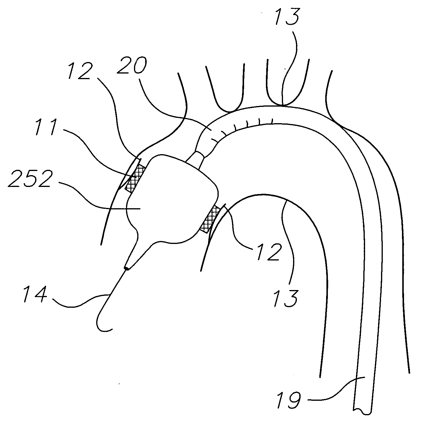
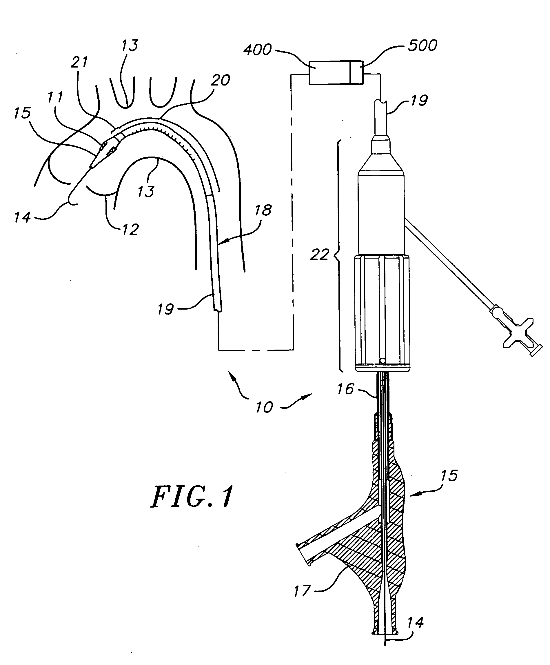
[0040] With reference now to FIG. 1, for purposes of illustration, one preferred embodiment of a heart valve delivery system 10 for delivering a prosthetic valve 11 to a diseased aortic valve 12 of a human heart is shown. The delivery system is well-suited for delivering the prosthetic valve 11 through a patient's vasculature and over an aortic arch 13 to a location adjacent the diseased valve 12.

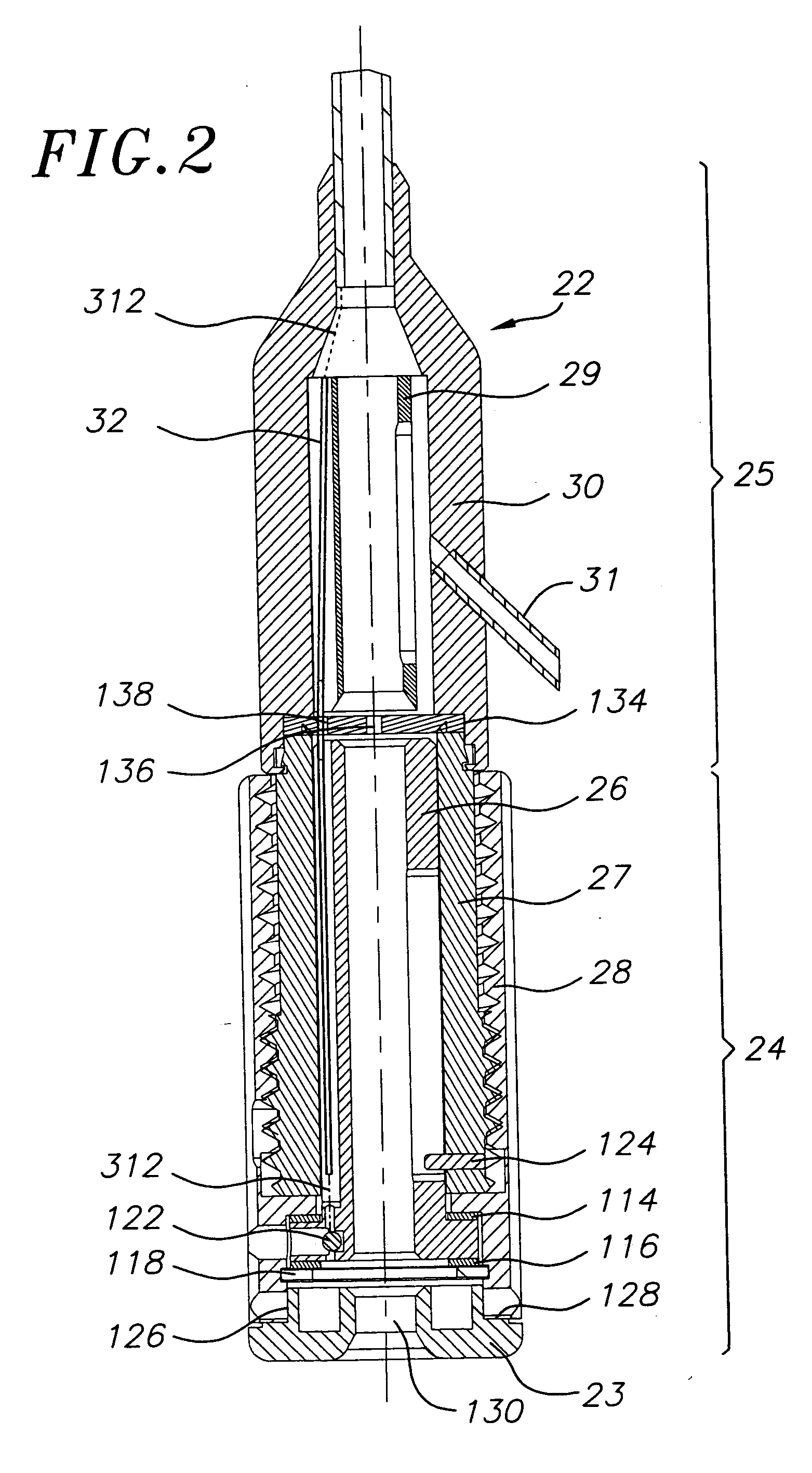
[0041] The delivery system 10 generally includes a guide wire 14 and a balloon catheter 15 configured for advancement over the guide wire 14. The prosthetic valve 11 is provided along the distal end portion of the balloon catheter. The balloon catheter 15 includes a tubular section 16 and a handle / support 17 at a proximal end of the tubular section 16. The tubular section 16 of the balloon catheter 15 is received within a delivery sleeve assembly 18. The delivery sleeve assembly generally comprises a sleeve 19, a steerable section 20 and a shroud section 21. A proximal end of the delivery ...


PUM


Abstract

A delivery system for delivering a prosthetic heart valve to a native valve site within the human vasculature. The prosthetic valve is disposed on a balloon at the end of a balloon catheter. The balloon catheter passes through a delivery sleeve assembly and handle. A pull wire travels from the handle to a distal end of the delivery sleeve assembly. Actuation of the handle pulls on the pull wire, which causes openings in a slotted tube of the delivery sleeve assembly to close, thus causing the delivery sleeve assembly to bend. A stretchable cover is placed over the slotted tube for biasing the steerable catheter toward a straight position. Once advanced to the native valve site, the prosthetic valve is deployed by inflating the balloon.

Description

BACKGROUND OF THE INVENTION [0001] The present invention relates to systems used to deliver a prosthetic valve to a heart. More specifically, the present invention is directed to an improved steerable delivery system for delivery of a prosthetic valve to a human heart. [0002] Catheters are known in the art and have been commonly used to reach locations inside the body that are not readily accessible by surgery or where access without surgery is desirable. The usefulness of catheters is largely limited by the ability of the catheter to successfully navigate through small vessels and around tight bends, such as around the aortic arch. [0003] Over the years, a variety of steerable catheters have been proposed for facilitating navigation through difficult vasculature. For example, some known devices employ a series of connected segments, each comprising a shape which allows the catheter to form a bent configuration adaptable to fit the particular need. The use of many connected segments...

Claims


Application Information

Patent Timeline
IPC IPC(8): A61F2/24
CPCA61F2/2433A61M25/0147A61M25/0138A61F2230/0069A61F2/2436A61F2/2427
Inventor TAYLOR, DAVID M.
Owner EDWARDS LIFESCIENCES CORP
Learn More