Light emitting diode package and method for making same

a technology of led package and light-emitting diodes, which is applied in the direction of printed circuit, sustainable manufacturing/processing, final product manufacturing, etc., can solve the problems of adding significant cost to the fabrication of led package, and the packaging is not well suited for multi-die array, so as to achieve cost-effective construction and versatility.

Inactive Publication Date: 2007-01-11
LIGHTING SCI GROUP
View PDF19 Cites 88 Cited by
  • Summary
  • Abstract
  • Description
  • Claims
  • Application Information

AI Technical Summary

Benefits of technology

[0005] The present invention relates to a LED package assembly including a PWB having one or more through-holes or apertures. Inserted into each of the apertures is a heat sink stud to form an integrated / monolithic assembly. According to an embodiment of the present invention, one or more light sources (i.e., LED die) may be placed (directly) on the heat sink stud, which carries away the heat generated by the LED die. In application, the assembly may be mounted on an external component, such as an external heat sink. Advantageously, the use of discretely-sized heat sink studs, integrated into the PWB allows for a compact, versatile and cost-efficient construction.
[0006] According to an embodiment of the present invention, the LED package assembly utilizes PWB techniques, SMT assembly techniques, and / or chip-on-board (COB) semiconductor die attachment techniques. Advantageously, the LED package assembly of the present invention reduces the cost and design cycle time for light emitting components, and is suitable for use in a variety of lighting applications including but not limited to general illumination, accent lighting, electronic display illumination, machine vision, etc. Advantageously, an array of LED die may be arranged in a single, low-cost, versatile package which is operable in high temperature environments.

Problems solved by technology

However, because conventional packages require a special, molded plastic housing (i.e., liquid crystal polymer) and optical element, the packages are not well suited for multi-die arrays that may be easily, quickly, and inexpensively modified to suit a particular lighting application.
Another fabrication and design challenge faced by high-temperature operation LED packages is the need to effectively manage the heat generated by the array of LEDs.
The metal carrier is generally composed of a relatively expensive material (e.g., molybdenum copper), adding significant cost to the fabrication of the LED package.

Method used


Image

  • Light emitting diode package and method for making same
  • Light emitting diode package and method for making same
  • Light emitting diode package and method for making same

Examples


Embodiment Construction

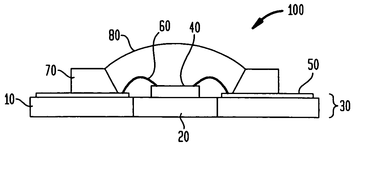
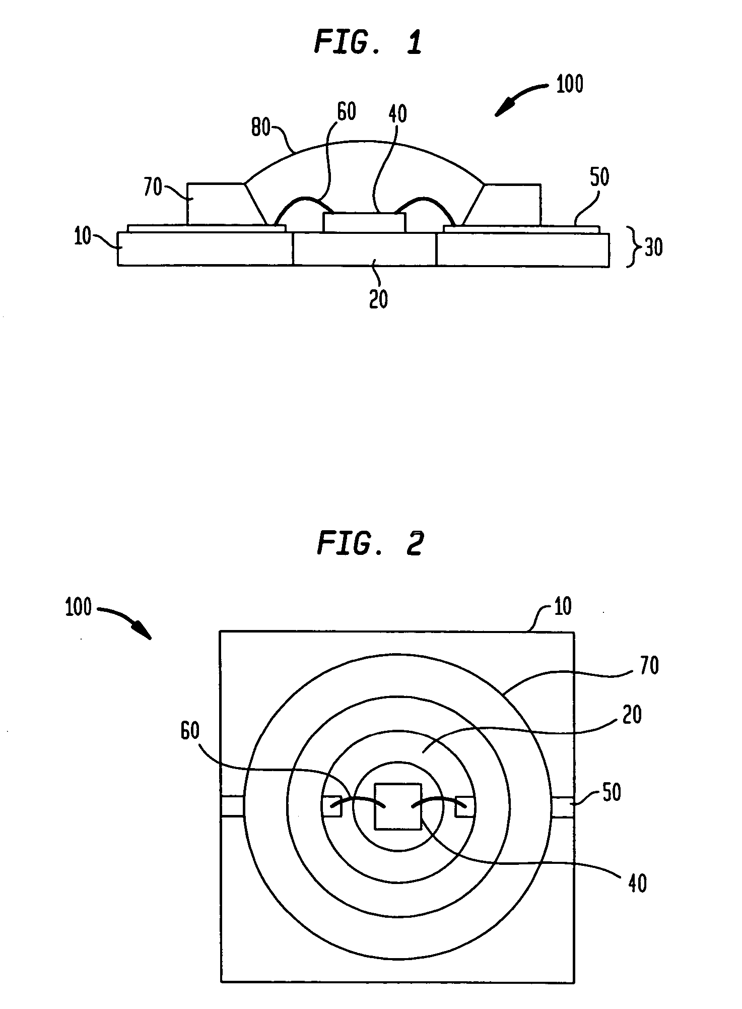
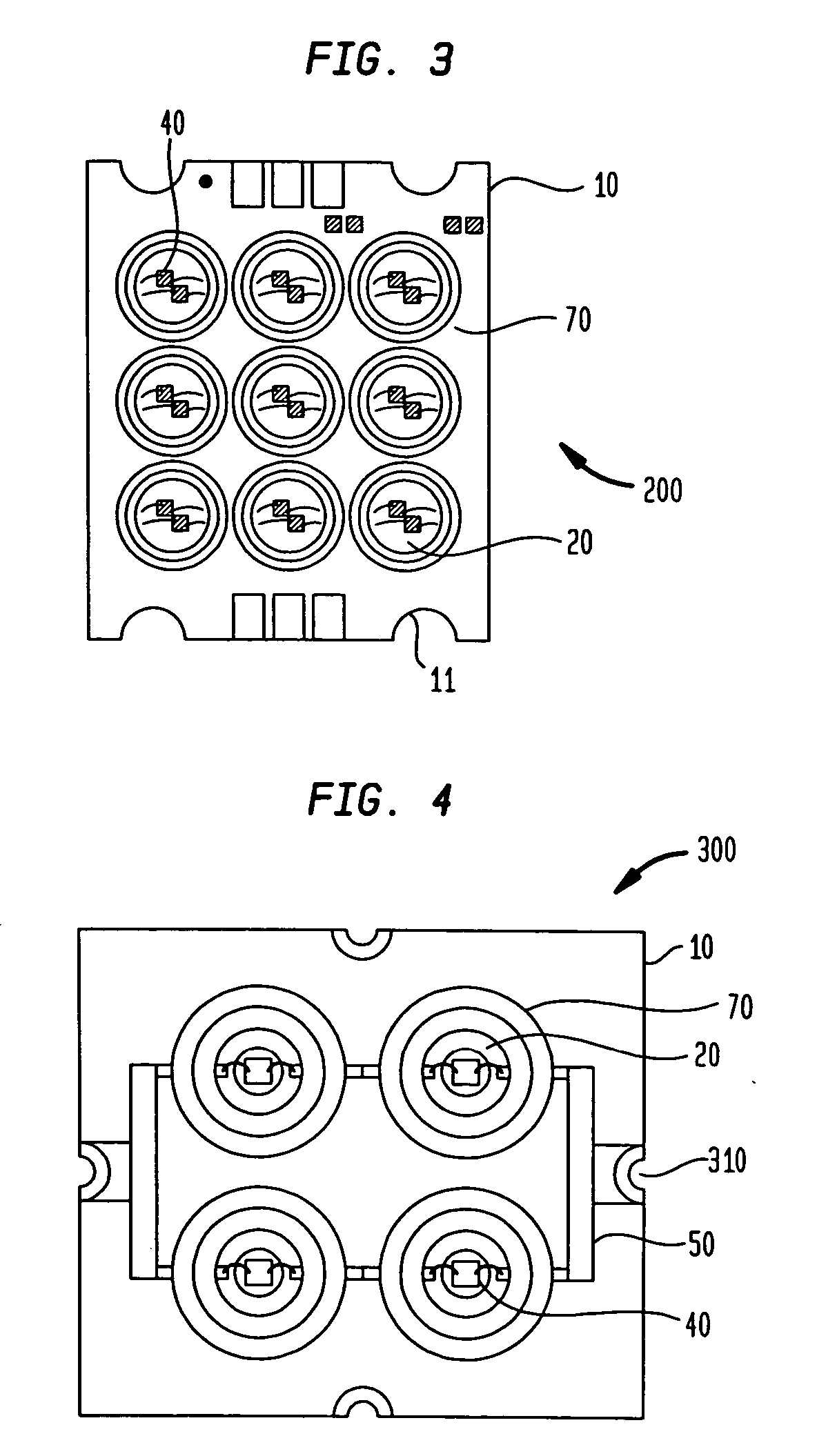
[0034] The present invention relates to light emitting packages, and methods for making same, wherein the light emitting package comprising at least one light emitting assembly including a printed wired board having one or more heat sink studs integrated therein to form a monolithic integrated base for mounting one or more light sources thereon. As used herein, the term “package” or “LED package” is intended to include, but is not limited to, an LED assembly comprising one LED or an array of LEDs, according to the present invention. As used herein, the term “array” is intended to refer to a plurality of elements, and is not intended to be limited to elements arranged in regular columns and / or rows. According to an embodiment of the present invention, the LED package may include an array of LED assemblies, with each LED assembly including an array of LED die.

[0035] According to an embodiment of the present invention, the one or more light sources comprise light emitting diode (LED) ...


PUM

PropertyMeasurementUnit
thickaaaaaaaaaa
thickaaaaaaaaaa
breakdown voltageaaaaaaaaaa

Abstract

A light emitting diode (LED) package for high temperature operation which includes a printed wire board and a heat sink. The LED package may include a formed heat sink layer, which may be thermally coupled to an external heat sink. The printed wire board may include apertures that correspond to the heat sink such that the heat sink is integrated with the printed wire board layer. The LED package may include castellations for mounting the package on a secondary component such as a printed wire board. The LED package may further comprise an isolator disposed between a base metal layer and one or more LED die. Optionally, the LED die may be mounted directly on a base metal layer. The LED package may include a PWB assembly having a stepped cavity, in which one or more LED die are disposed. The LED package is advantageously laminated together using a pre-punched pre-preg material or a pressure sensitive adhesive.

Description

CROSS-REFERENCE TO RELATED APPLICATIONS [0001] This application claims the benefit of U.S. Provisional Application No. 60 / 694,788 filed on Jun. 27, 2005, U.S. Provisional Application No. 60 / 738,478 filed Nov. 21, 2005, and U.S. Provisional Application No. 60 / 763,828 filed Jan. 31, 2006. U.S. Provisional Application Nos. 60 / 694,788, 60 / 738,478, and 60 / 763,828 are hereby incorporated by reference herein.FIELD OF THE INVENTION [0002] The present invention relates generally to a light emitting diode (LED) package and method for making same, and, in particular to a LED package adapted for high temperature operation. BACKGROUND OF THE INVENTION [0003] Conventional light emitting diode (LED) packages include a specialized, moldable plastic housing having a separate transparent cover exhibiting specific optical properties. Generally, these LED packages are designed exclusively for direct surface mount technology (SMT) connection to a printed wire board (PWB). However, because conventional p...

Claims


Application Information

Patent Timeline
Patent Type & Authority Applications(United States)
IPC IPC(8): H01L29/768H01L33/48H01L33/64
CPCH01L25/0753Y10T156/13H01L33/641H05K1/021H05K1/141H05K1/182H05K3/0061H05K3/3442H05K3/403H05K2201/09127H05K2201/09181H05K2201/09845H05K2201/10106H05K2203/063H01L2224/48137H01L2224/48227Y10T29/49139Y10T29/49155Y10T29/49126H01L33/486Y02P70/50
Inventor MAZZOCHETTE, JOSEPH
Owner LIGHTING SCI GROUP
Why Eureka
Try Eureka