Balloon control device for endoscopic apparatus

Inactive Publication Date: 2007-01-11
FUJI PHOTO OPTICAL CO LTD
View PDF5 Cites 21 Cited by
  • Summary
  • Abstract
  • Description
  • Claims
  • Application Information

AI Technical Summary

Benefits of technology

[0014] According to the present invention, as a buffering section is provided in a tube path through which a fluid flows and the buffering section buffers a change in pressure of the fluid and restrains a rap

Problems solved by technology

With use of a filter for the trap, however, there is a problem that a resistance in a tube path is increased, and that this causes a large difference between the pressure in the tube path in the device body and the pressure in a balloon.
If there is a large difference between the pressure in the tube path in the device body and the pressure in a balloon, the measured value by the pressure sensor is different from an actual inner pressure of a

Method used


Image

  • Balloon control device for endoscopic apparatus
  • Balloon control device for endoscopic apparatus
  • Balloon control device for endoscopic apparatus

Examples


Example

[0025] Now, a preferred embodiment of a balloon control device for an endoscopic apparatus according to the present invention will be described in detail with reference to the accompanying drawings.

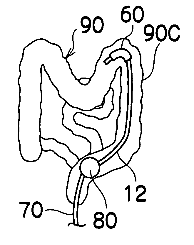
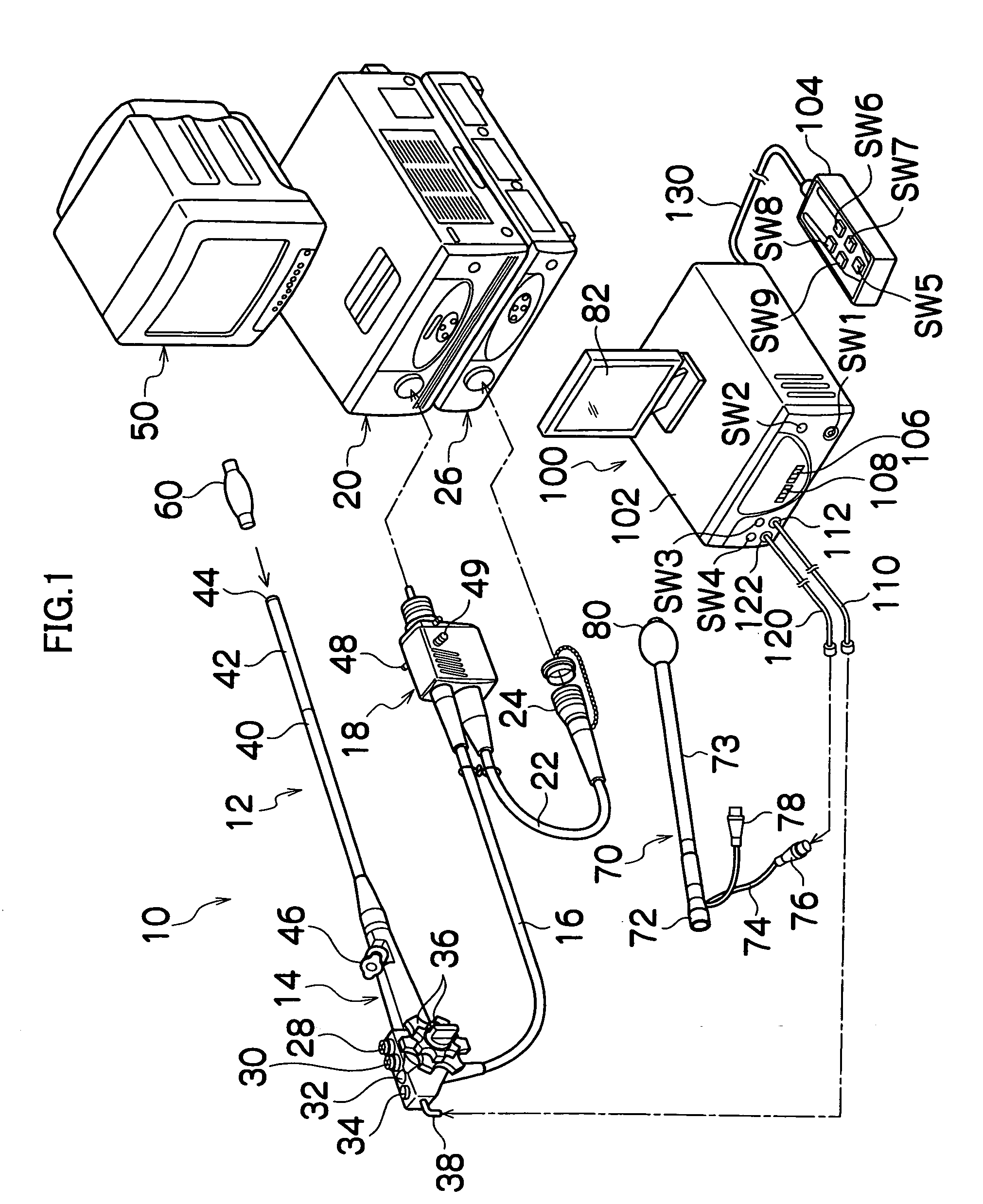
[0026]FIG. 1 is a system configuration diagram to show an embodiment of an endoscopic apparatus to which a balloon control device is applied according to the present invention. As shown in FIG. 1, an endoscopic apparatus generally comprises an endoscope 10, an insertion assisting tool 70, and a balloon control device 100.

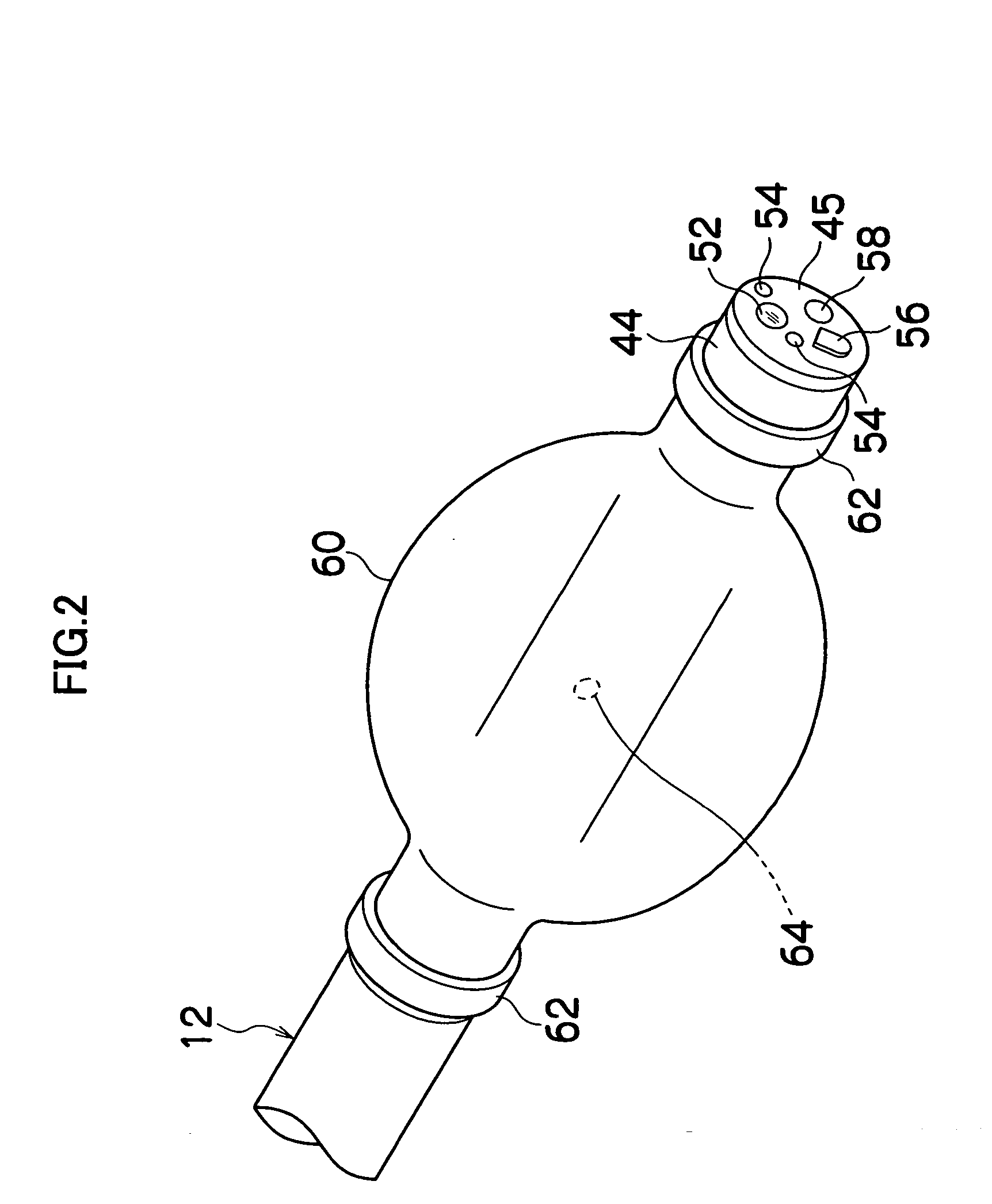
[0027] The endoscope 10 comprises a hand-held control section 14 and an inserting section 12 connected to the hand-held control section 14 to be inserted into a body cavity. The hand-held control section 14 is connected to a universal cable 16 having an end which is provided with an LG connector 18. The LG connector 18 is removably coupled to a light source device 20 which sends an illumination light to an illumination optical system 54 which will be explained below (se...


PUM


Abstract

The present invention provides a balloon control device for an endscopic apparatus, which supplies and sucks a fluid to and from either a balloon mounted to an inserting section of the endscopic apparatus or a balloon mounted to an insertion assisting tool covering the inserting section for assisting the insertion of the inserting section, comprising a buffering section in a tube path through which a fluid flows so as to buffer a change in pressure of the fluid, in order to control an inner pressure of a balloon by reducing a difference between a pressure in the balloon and a pressure in a tube path.

Description

BACKGROUND OF THE INVENTION [0001] 1. Field of the Invention [0002] The present invention relates to a balloon control device for an endoscopic apparatus, in particular, a balloon control device which controls balloons in an endoscopic apparatus for observing lower gastrointestinal tract such as small intestine or colon. [0003] 2. Description of the Related Art [0004] In inserting an inserting section of an endoscope into lower gastrointestinal tract such as small intestine, if the inserting section is simply pushed down there, the pushing power cannot be transmitted enough to a distal end of the inserting section and it is difficult to insert the inserting section into the lower part. For example, when an inserting section is unnecessarily bent or deflected, the inserting section cannot be inserted further into the lower part. So, methods have been proposed for preventing any excess bend or deflection of an inserting section by inserting the inserting section of an endoscope into a...

Claims


Application Information

Patent Timeline
IPC IPC(8): A61M31/00A61M37/00
CPCA61B1/00082A61B1/00101A61B1/31A61B1/015A61B1/018A61B1/0051
Inventor SEKIGUCHI, TADASHIKUMEKAWA, TAKASHI
Owner FUJI PHOTO OPTICAL CO LTD
Why Eureka
Try Eureka