
Ablation and micro-needles

a micro-needle and needle technology, applied in the field of injection delivery, can solve the problems of syringes not being useful for self-administration by patients, and affecting the effect of needle engagemen

Inactive Publication Date: 2007-01-11
MEDICAL MICRODEVICES
View PDF37 Cites 98 Cited by
  • Summary
  • Abstract
  • Description
  • Claims
  • Application Information

AI Technical Summary

Benefits of technology

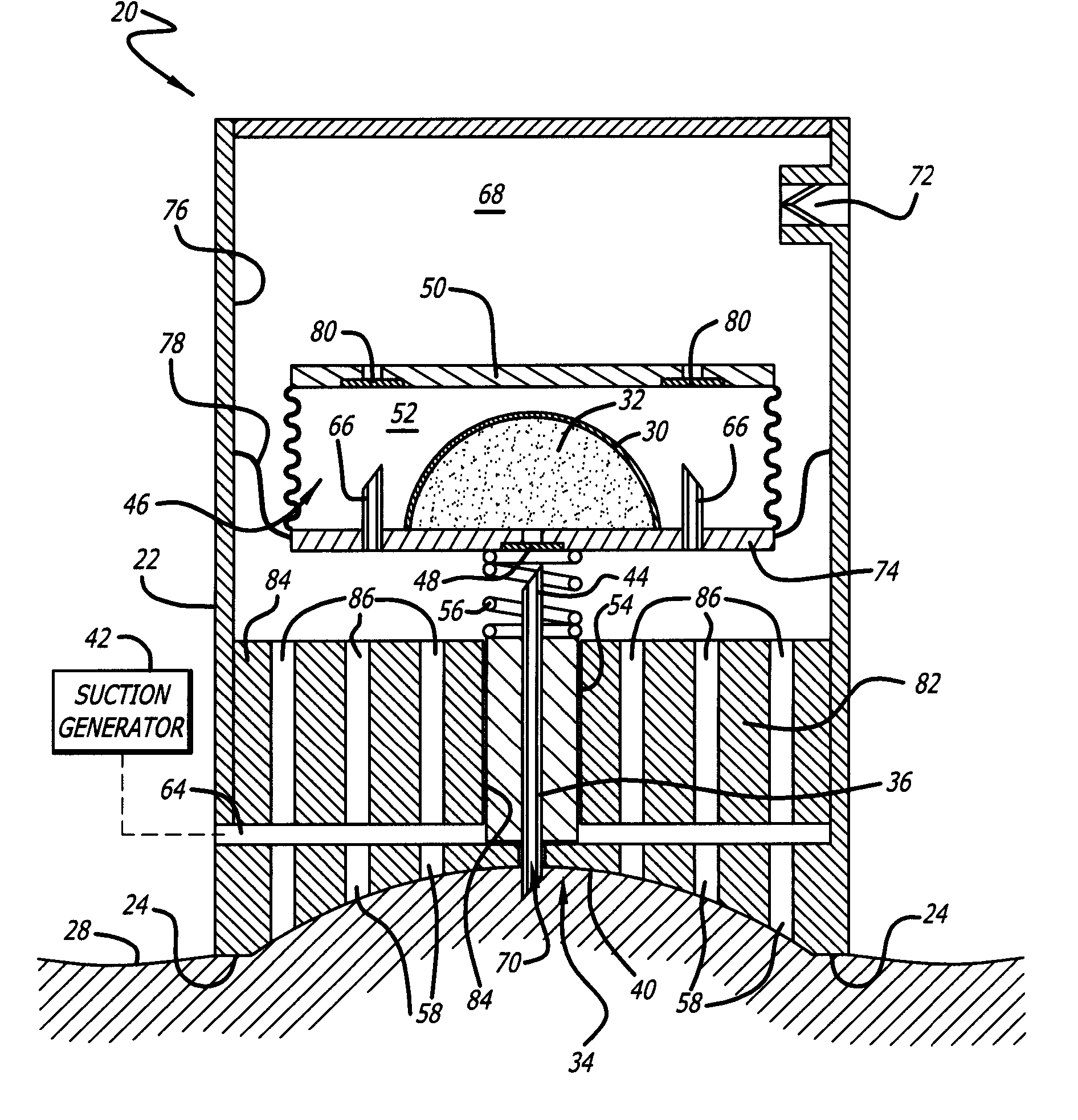
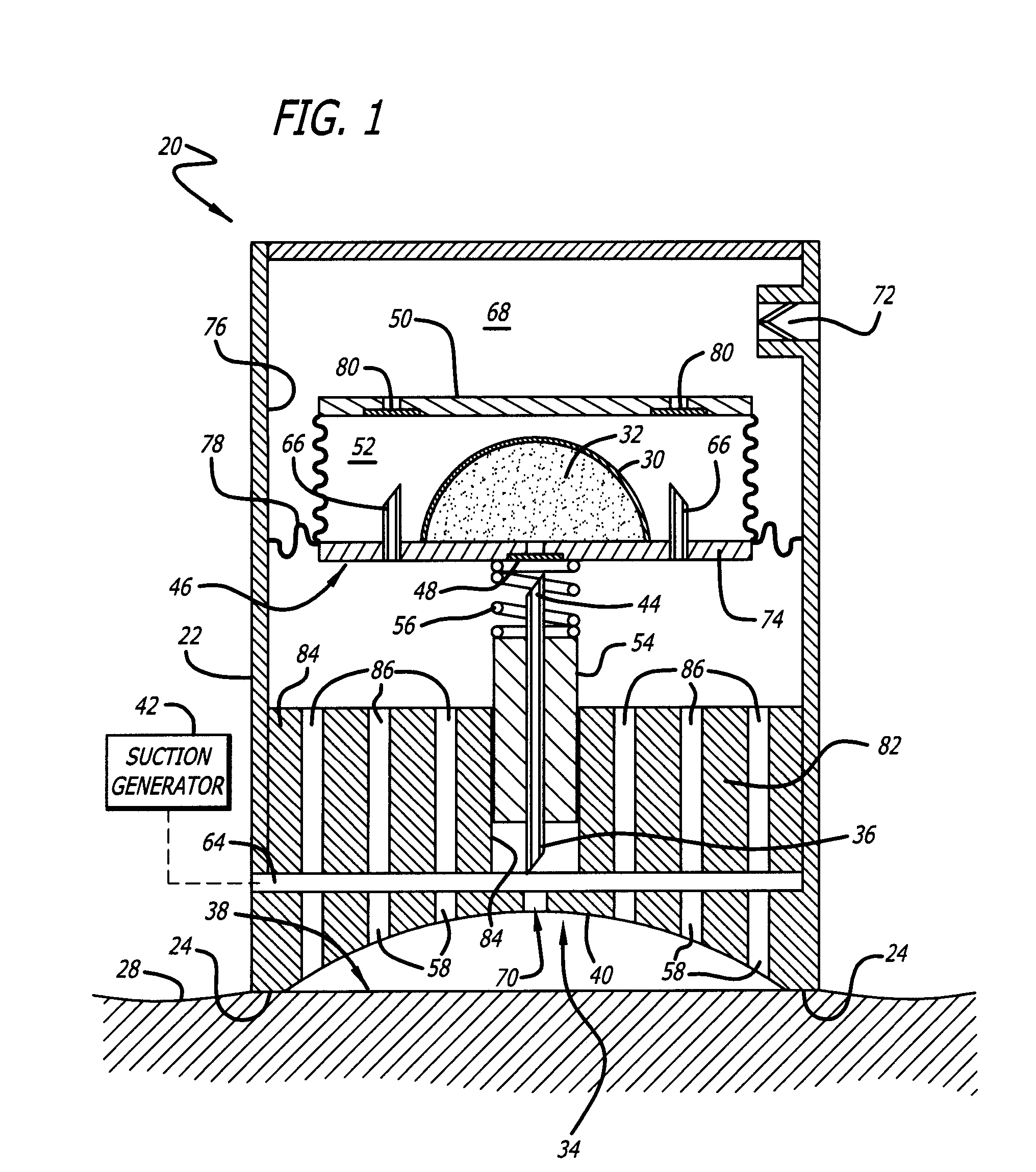
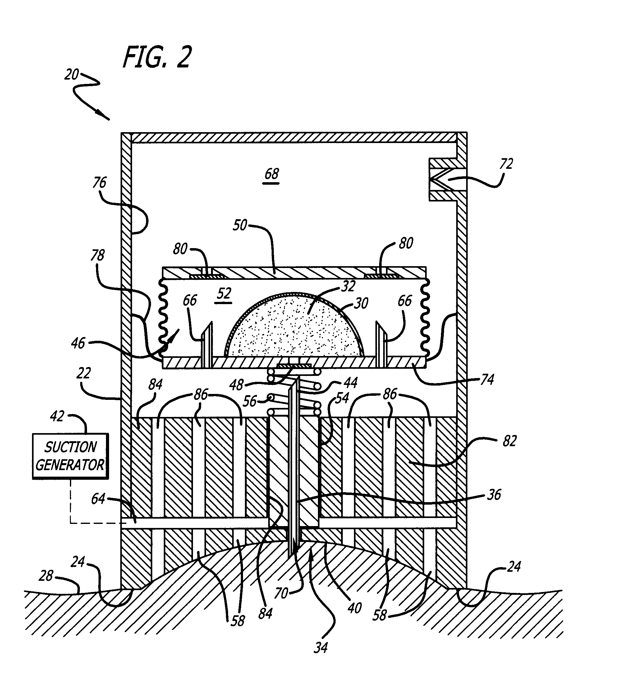
[0014] The device includes a mounting for supporting a needle. The suction causes the needle and its mounting to move through the transverse area. The means for providing a suction force causes the movement of the needle mounting and thereby causes the needle to move between a position of repose relatively withdrawn from the transverse area and a position extending through the transverse area.
[0045] In some uses applying electromagnetic energy through needles or micro-needles creates heat and at about 50 degrees Celsius causes irreversible cell death and tissue ablation. Needle delivery of energy increases the depth of ablation and uniformity fluid irrigation with, for example, saline, through the hollow needle decreases the impedance at tissue contact. This prevents tissue sticking to the ablation needle and prevents tissue char.

Problems solved by technology

These all suffer from one or another drawback.
A conventional method for administration is a hypodermic syringe, but this has disadvantages.
Particularly, syringes may not be useful for self-administration by patients because of the dangers of embolisms arising from the introduction of air bubbles into the bloodstream, incorrect dosing and accidental infections.
Some syringes are pre-filled, which does correct some of the disadvantages, but difficulties, however, still arise with the complexity of manipulating the syringes in a smooth or uniform fashion with a single hand.
Additionally, some patients have the fear of micro-needles and the sophistication and complexity of mechanical arrangements for activating self-administering syringes generally continues to be a disadvantage.
Other disadvantages arise from the system for loading pre-prepared syringes with mechanisms and propellants to activate the syringes throughout the anticipated shelf life of the product.
Needle-less devices are known, but often these require superior dexterity for use and this is also a disadvantage for effecting injections by patients or doctors.
Many other disadvantages can arise from the complexity of different systems.
In some uses applying electromagnetic energy through needles or micro-needles creates heat and at about 50 degrees Celsius causes irreversible cell death and tissue ablation.

Method used


Image

  • Ablation and micro-needles
  • Ablation and micro-needles
  • Ablation and micro-needles

Examples


Embodiment Construction

[0070] The disclosure is described with reference to the accompanying drawings.

[0071] A device, system and method is for delivery of fluids by injection to the cutaneous or subcutaneous region of a living body under the effects of suction or a vacuum.

[0072] The device 20 includes a housing 22 having a peripheral edge 24 and a needle 26 in the housing for piercing the cutaneous layer 28. There is a bladder 30 for containing fluid 32 for injection below the cutaneous layer 28, and an area 34 transversely within peripheral edge 24 of the housing 22 and through which the proximal end 36 of the needle 26 may be directed.

[0073] The area 34 is for receiving the surface 38 of the cutaneous layer 28 about which the proximal end 36 of the needle 26 is to pierce to effect an injection of fluid 32. The area 34 includes a surface 40, the surface being for receiving the cutaneous layer 28 under action of the suction force, and thereby stabilize the cutaneous layer prior to and during piercing ...


PUM


Abstract

A device permits effective engagement of micro-needles with a cutaneous layer thereby to permit for a substance to pass effectively to the cutaneous layer. A flexible or non-flexible material supports an array of micro-needles for receiving the surface of the cutaneous layer so that the proximal ends of the micro-needles pierce to effect a passage of a substance with the micro-needles to the cutaneous layer. A passageway or bladder acts on the substrate to cause the proximal ends of the micro-needles to pass to the cutaneous layer for passage of a substance associated with the micro-needles to the cutaneous layer. The bladder includes apertures located about and spaced from the micro-needles such that suction transmitted though the apertures. The micro-needles are mounted with a movable first substrate. In one form, the first substrate includes a surface with concavities and the micro-needles are mounted in the concavities, and the apertures are located in the concavities. In another form the surface is substantially flat. There can be a third layer spaced relative to the second substrate layer at least partly forming a chamber between the second layer and third layer. There can be a biasing device for urging the first substrate from the cutaneous layer.

Description

RELATED APPLICATION [0001] This application is a divisional of U.S. application Ser. No. 11 / 428,303, filed Jun. 30, 2006, which is a continuation-in-part of U.S. application Ser. No. 10 / 906,602, filed Feb. 25, 2005, which is a divisional of U.S. application Ser. No. 10 / 290,819, filed Nov. 8, 2002 and issued as U.S. Pat. No. 6,896,666 on May 24, 2005. The contents thereof are incorporated by reference in their entireties.BACKGROUND OF THE DISCLOSURE [0002] This disclosure relates to injection delivery cutaneously or subcutaneously. In particular, it relates to a system for stabilizing tissue then facilitating injection of fluids into a body which may be human or animal. More specifically it relates to micro-needles. [0003] Many systems have been devised for the effective delivery of injectable material such as drugs into a body. These all suffer from one or another drawback. [0004] A conventional method for administration is a hypodermic syringe, but this has disadvantages. Particula...

Claims


Application Information

Patent Timeline
Patent Type & Authority Applications(United States)
IPC IPC(8): A61B18/18A61B18/02A61B18/14A61M5/142A61M5/28A61M5/42A61M37/00
CPCA61B18/02A61B18/1477A61B2018/1425A61M5/14248A61M5/282A61M2230/00A61M5/425A61M37/00A61M37/0015A61M2005/14252A61M2005/1426A61M5/42
Inventor KOCHAMBA, GARY S.
Owner MEDICAL MICRODEVICES
Learn More