Prostheses

a technology of cruciate ligaments and prostheses, applied in the field of prostheses, can solve the problems of significant patella-femoral, injury, and other knee function problems, and achieve the effect of improving functioning

Inactive Publication Date: 2007-01-11
FINSBURY DEV
View PDF18 Cites 28 Cited by
  • Summary
  • Abstract
  • Description
  • Claims
  • Application Information

AI Technical Summary

Benefits of technology

[0033] In a still further alternative arrangement, the means for connecting the replacement ligament may be provided on the bar. For example, the bar may include a notch into which the ligament may be engaged. In another arrangement an aperture may be provided in the bar through which the ligament can be passed. In this latter arrangement the replacement ligament may be provided with a pivotable pin which can be threaded through the aperture and then pivoted to a position which will prevent the ligament from being pulled back through the aperture.
[0036] In one arrangement, the bar may be provided with anti-movement means which will prevent one or more of rotation, medial-lateral movement, and anterior-posterior movement, when located in the intercondylar notch.
[0043] It will be understood that for the correct functioning of the replacement ligament, the bar is preferably located to lie on the centre of rotation of the knee femur as determined by the articular surfaces of the femur whether a natural or replacement knee femur. Where the bar is to be placed in a bore in the condyle, it may be desirable to utilise a jig to guide the axial direction of the drill which will be used to produce the bore into which the bar will be placed. However, in some circumstances it may be desirable for the surgeon to select a different position for the bar where that will provide improved functioning. For example, a planned eccentricity for the posterior cruciate ligament can induce so called “roll back” of the femur on the tibia and a planned eccentricity for the anterior cruciate ligament may induce “roll forwards”.

Problems solved by technology

The posterior and / or anterior cruciate ligaments may become damaged through trauma, such as a sporting injury, or accident.
However, even if the tear heals successfully, the ligament may be too lax for correct functioning.
Chronic cruciate ligament laxity or rupture may cause significant patella-femoral, and other knee function problems, due to instability of the femur on the tibia.
More severe injuries can cause damage that will not heal to provide natural function and stability.
Although ligament reconstructive techniques are performed relatively successfully in the unreplaced knee, they generally are difficult and may leave the patient in a worsening position than if there had been no treatment.
This is usually due to the implant having no intrinsic anterior / posterior stability.
Additionally or alternatively poor placement of the implants will result in laxity in either, or both of, extension and flexion.
However, the stability is only provided for a limited range of motion.
In particular, the level of stability required for walking may not be provided.
A further disadvantage of these prostheses is that the forces that the post and cam mechanism exert are not easy to predict or measure and are therefore not designed to resist for long implantation periods.
This can lead to the parts wearing badly or even fracturing.
This wear and stress can lead to the fixation between the implant and the bone being too high or changing, which in turn may lead to extra loosening loads being experienced.
This in turn will lean to relatively early failure of the joint.
A still further disadvantage of posterior stabilised knee prostheses is that in order to insert the prostheses, the knee must be relatively lax.
However, these add a further engineering complexity that predisposes their failure.
Whilst such ligaments may be useful, the harvesting step increases the cost of the operation and the suffering to the patient.
However, known artificial ligaments are generally unable to deal with the stresses and fatigue caused in the ligament at the femoral insertion point due to sustained repeated flexural motion.
Whilst replacement ligaments have offered some success with natural knee joints, artificial replacement ligaments have not generally been provided which can successfully be used with prosthetic knees.

Method used


Image

  • Prostheses
  • Prostheses
  • Prostheses

Examples


Embodiment Construction

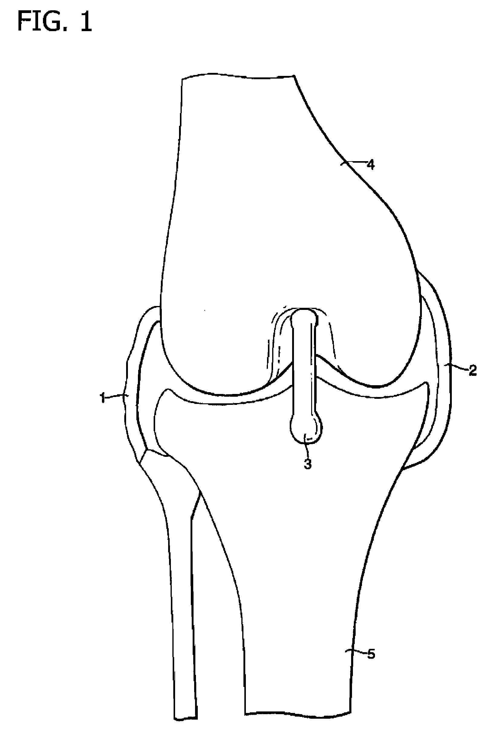
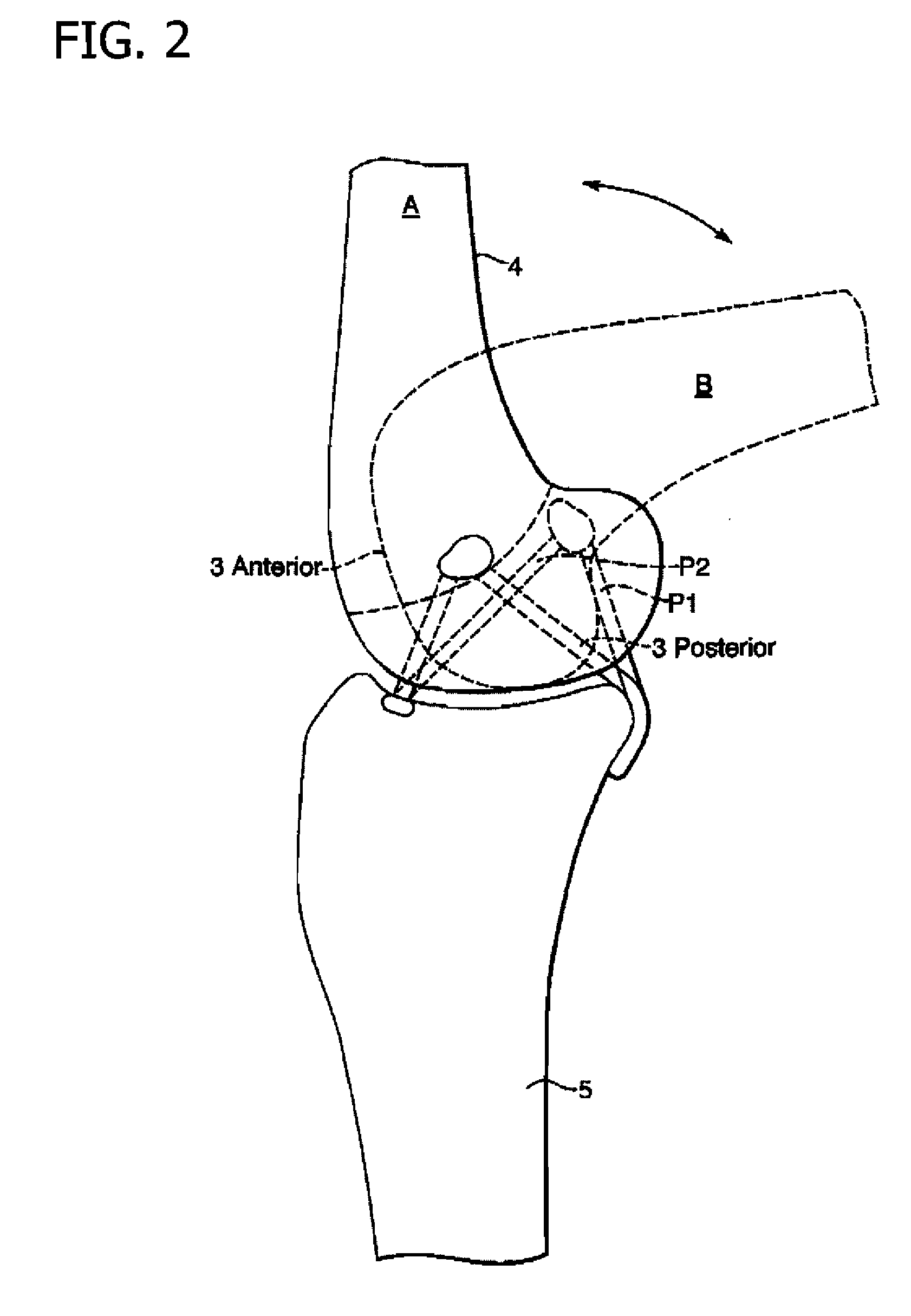
[0087] The present invention will now be described with reference to a knee prosthesis. However, it will be understood that it may be utilised with a normal knee.

[0088] As illustrated in FIG. 6 a jig 11 comprises rods 9 connected to a guide 10. These are angled such they represent the arms of a segment of a circle. The arms are in the same plane and are of the same length. Fingers 12 extend from the end of the arms.

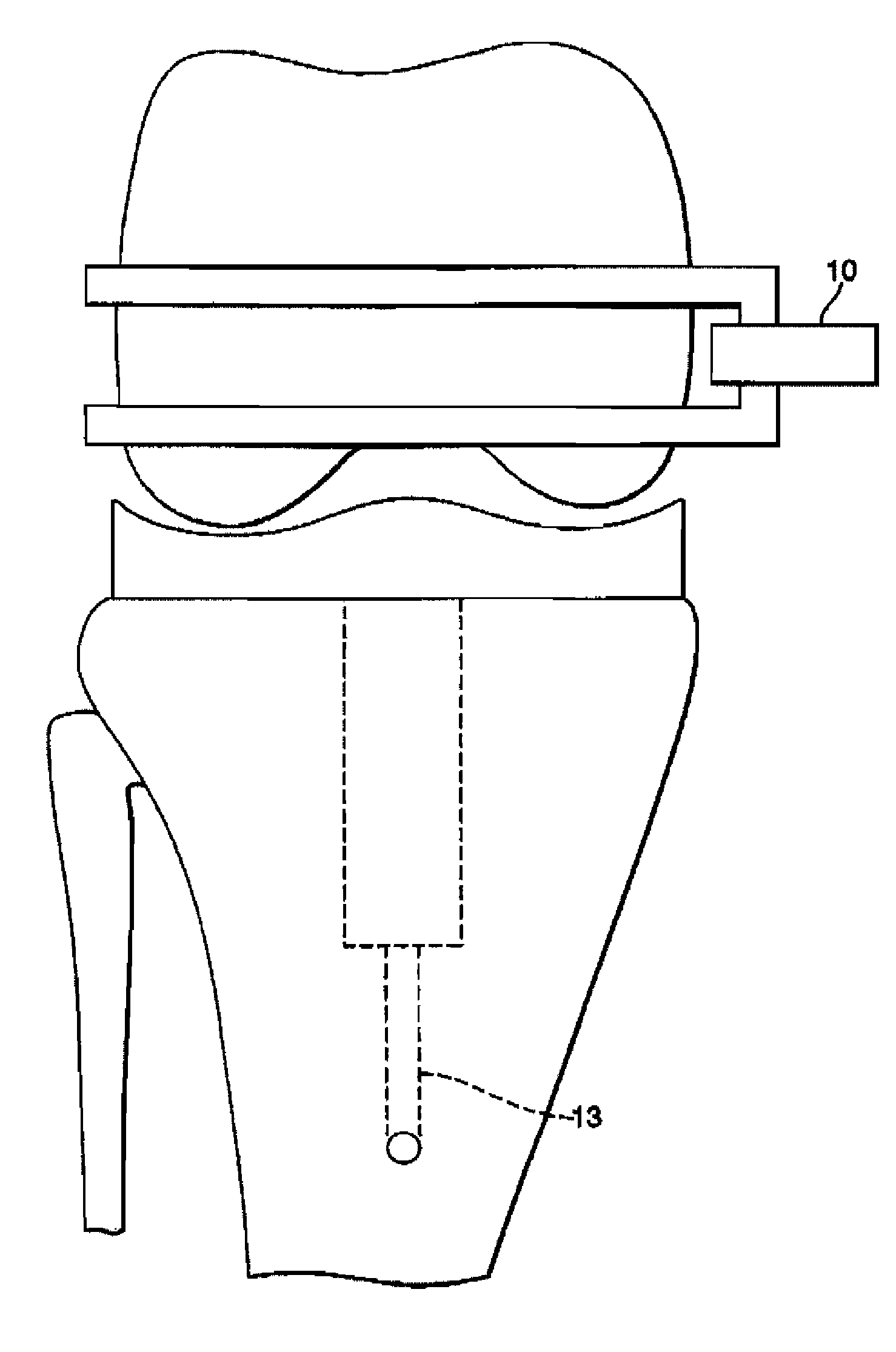
[0089] The jig 11 is then placed against the exposed knee which is positioned in flexion as illustrated in FIGS. 7 and 8. The fingers 12 are located against the face of the condyles with an upper finger being placed at the end of the femur 3. The aperture 10 lies on the epicondylar axis. As illustrated in FIG. 8, the aperture may be a drill guide.

[0090] Once the drill guide 12 is correctly positioned, it may be stabilised using pins or may be clamped on either side of the inter-condylar notch or the femur. The femoral bore will then be made and the jig removed.

[0091] ...


PUM


Abstract

A replacement ligament prosthesis including an elongate replacement ligament having a femoral end and a tibial end. The prosthesis includes a bar, which in use will extend between the medial and lateral condyles of a femur and across the intercondylar notch, and to which the femoral end of the elongate replacement ligament will be fixed. The prosthesis also includes a fixing means, which in use will fasten the tibial end of the elongate replacement ligament to the tibia.

Description

BACKGROUND OF THE INVENTION [0001] The present invention relates to a replacement anterior and / or posterior cruciate ligament in the knee. In addition, the present invention relates to a replacement collateral ligament for the knee. For ease of reference the replacement anterior and / or posterior cruciate ligament and the replacement collateral ligament will hereinafter be collectively referred to simply as the “replacement ligament”. More particularly, the present invention relates to a replacement cruciate ligament which is suitable for use with a prosthetic knee. In alternative arrangements, the present invention also relates to a guide to assist in the placement of a replacement of a cruciate ligament, a kit of components for use in the implantation of a replacement cruciate ligament and a method of inserting the replacement cruciate ligament. [0002] The human knee is a complex joint which is stabilised by several ligaments. The four most important of which are the lateral and me...

Claims


Application Information

Patent Timeline
Patent Type & Authority Applications(United States)
IPC IPC(8): A61F2/08A61B17/17A61F2/38
CPCA61B17/1714A61B17/1764A61F2/0805A61F2002/087A61F2/3836A61F2002/0852A61F2002/0858A61F2/0811
Inventor TUKE, MICHAEL ANTONY
Owner FINSBURY DEV
Why Eureka
Try Eureka