Muffling apparatus having exhaust emission purifying function

a technology of exhaust gas and purification function, which is applied in the direction of mechanical apparatus, engine components, machines/engines, etc., can solve the problems of inability to achieve satisfactorily purification performance, inability to achieve nox purification efficiency, and inability to achieve nox purification performance. , to achieve the effect of improving nox purification performance, improving nox reduction performance, and increasing nox purification efficiency

Active Publication Date: 2007-01-18
VOLVO LASTVAGNAR AB +2
View PDF5 Cites 17 Cited by
  • Summary
  • Abstract
  • Description
  • Claims
  • Application Information

AI Technical Summary

Benefits of technology

[0017] As described in the foregoing, In accordance with the present invention, since the vortex traveling in the vertical direction is generated at the turning portion, the unequal flow of the exhaust gas entering into the reduction catalytic converter is reduced, and also, the diffusion of the liquid reducing agent into the exhaust gas is promoted, so that the distribution of the liquid reducing agent in the exhaust gas is equalized. Therefore, the NOx purification efficiency in the reduction catalytic converter is increased, and the NOx purification performance can be improved.
[0018] Further, the plurality of opening portions in the ring member serving as the diffusing member are formed to be arranged at non-uniform distribution in the circumferential direction, so that the flow direction of the exhaus...

Problems solved by technology

However, in the muffling apparatus of the structure in which the turning portion is disposed, since the structure thereof is such that the exhaust gas flow direction is forcibly changed at the turning portion, the flow of the exhaust gas flow must become unequal.
Accordingly, the flow of the exhaust gas entering into the reduction catalytic converter is inconstant, which causes uneven distribution of the liquid reducing agent when it flows into the reduction catalytic converter and hence, there might be such a possibility that the ...

Method used


Image

  • Muffling apparatus having exhaust emission purifying function
  • Muffling apparatus having exhaust emission purifying function
  • Muffling apparatus having exhaust emission purifying function

Examples


Embodiment Construction

[0026] Hereunder, there will be described a muffling apparatus having an exhaust emission purifying function in accordance with the present invention, based on the appended drawings.

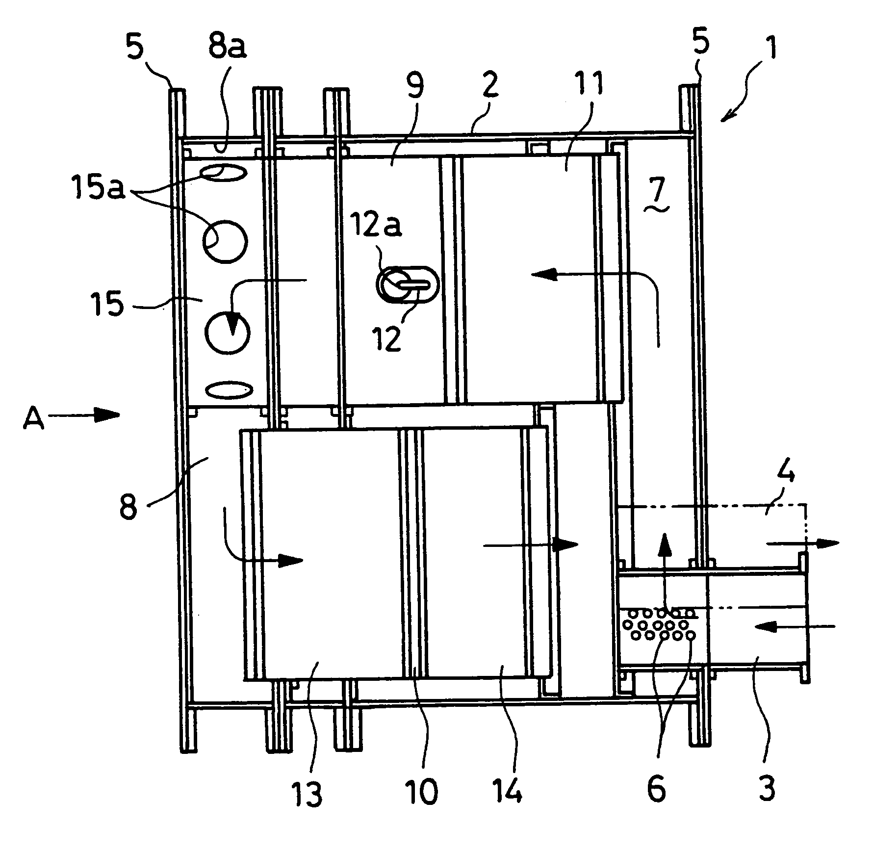
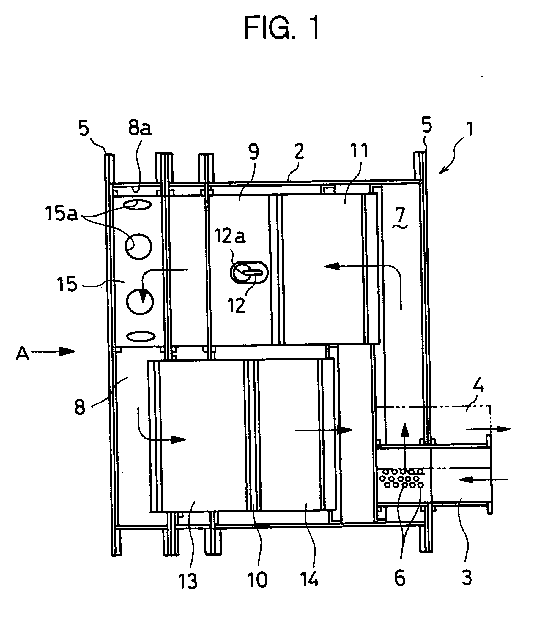
[0027]FIG. 1 is a diagram showing an internal structure of a muffling apparatus provided with an exhaust emission purifying function according to one embodiment of the present invention.

[0028] In FIG. 1, in the muffling apparatus 1 in this embodiment, on a right-hand side face (in the figure) of a case 2, an exhaust gas inlet portion 3 is disposed and an exhaust gas discharge portion 4 (shown by two-dot chain line in the figure) is disposed on a front side (in the figure) of the exhaust gas inlet portion 3. Further, on an outer periphery of the case 2, a fitting flange portion 5 is disposed for fixing the muffling apparatus 1 to an appropriate position of a vehicle. To the inside of the case 2, there are formed an extension chamber 7 which is communicated with the exhaust gas inlet portion 3 via a larg...


PUM


Abstract

A muffling apparatus 1 of the present invention having an exhaust emission purifying function, including a turning portion 8 in an inside of an exhaust gas flow passage, and having an injection nozzle 12 disposed in an upstream side exhaust gas flow passage 9 of the turning portion 8, for injection-supplying a liquid reducing agent; and a reduction catalytic converter 13 disposed in a downstream side exhaust gas flow passage 10 of the turning portion 8, for reductively purifying nitrogen oxides with the liquid reducing agent. The apparatus further includes a diffusing member 15, which generates a vortex flow of a gas traveling in a vertical plane of the turning portion 8 to diffuse the liquid reducing agent.

Description

[0001] This application is a continuation of PCT / JP2005 / 004542, filed on Mar. 15, 2005.BACKGROUND OF THE INVENTION [0002] 1. Field of the Invention [0003] The present invention relates to a muffling apparatus having an exhaust emission purifying function of reducing NOx in the exhaust gas from, for example, a vehicle engine and the like to purify the exhaust gas using a liquid reducing agent and a reduction catalytic converter, and in particular, to a technology for improving the NOx reduction performance in a muffling apparatus having a structure for forcibly turning a flow direction of the exhaust gas back inside thereof and capable of exhibiting an exhaust emission purifying function in addition to the muffling function. [0004] 2. Description of the Related Art [0005] As an exhaust emission purifying system for eliminating NOx contained in the exhaust gas of an engine, there has been proposed an exhaust emission purifying apparatus for injection-supplying a liquid reducing agent ...

Claims


Application Information

Patent Timeline
IPC IPC(8): F01N3/00F01N3/10F01N3/24F01N3/08F01N3/20F01N3/28F01N3/34F01N13/02
CPCF01N1/084F01N1/089F01N3/2066F01N3/2885F01N5/04F01N2230/04F01N13/0097F01N2470/00F01N2610/02F01N2610/08Y02T10/16Y02T10/24F01N2240/20Y02T10/12
Inventor AMEMIYA, TOMOKOMOCHIZUKI, TAKEFUMIKANAYA, ISAMUSHIRAI, DAISUKEHIRAMOTO, HITOSHI
Owner VOLVO LASTVAGNAR AB
Why Eureka
Try Eureka