
Impact resistance acoustic treatment

a technology of acoustic treatment and impact resistance, which is applied in the direction of instruments, machines/engines, transportation and packaging, etc., can solve the problem of thin face sheet being vulnerable to high velocity impacts, and achieve the effect of reducing the restriction of sound energy

Inactive Publication Date: 2007-01-18
UNITED TECH CORP
View PDF7 Cites 8 Cited by
  • Summary
  • Abstract
  • Description
  • Claims
  • Application Information

AI Technical Summary

Benefits of technology

[0010] Accordingly, the liner assembly of this invention provides an acoustically active panel that provides the desired strength to protect against impacts and foreign object damage.

Problems solved by technology

The thin face sheet is vulnerable to high velocity impacts and therefore is not utilized in areas of the liner assembly that are prone to high velocity impact from foreign objects.

Method used


Image

  • Impact resistance acoustic treatment
  • Impact resistance acoustic treatment
  • Impact resistance acoustic treatment

Examples


Embodiment Construction

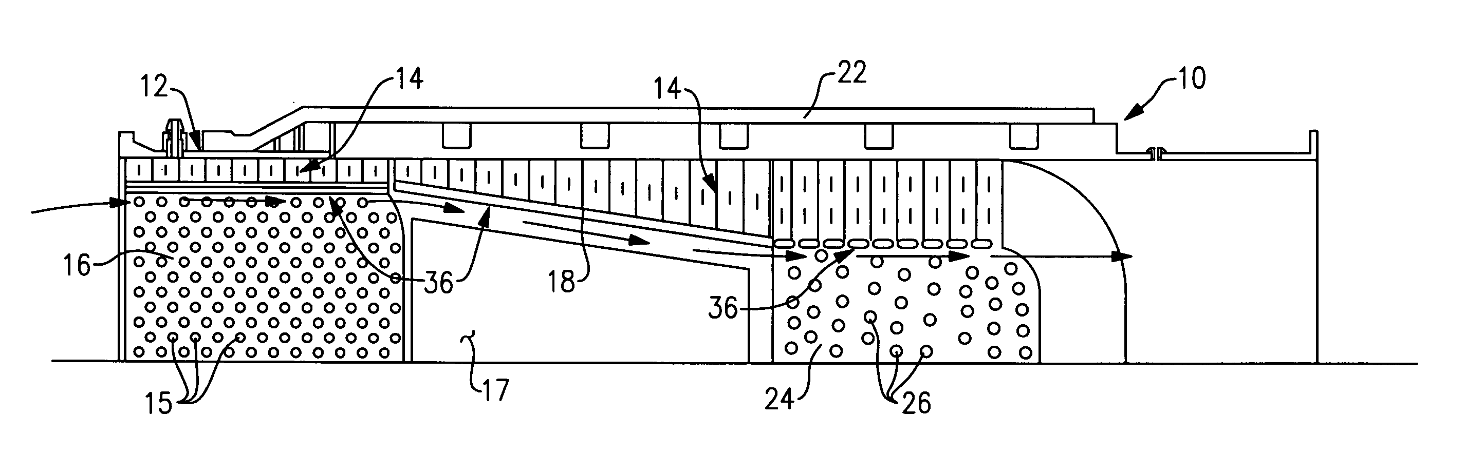
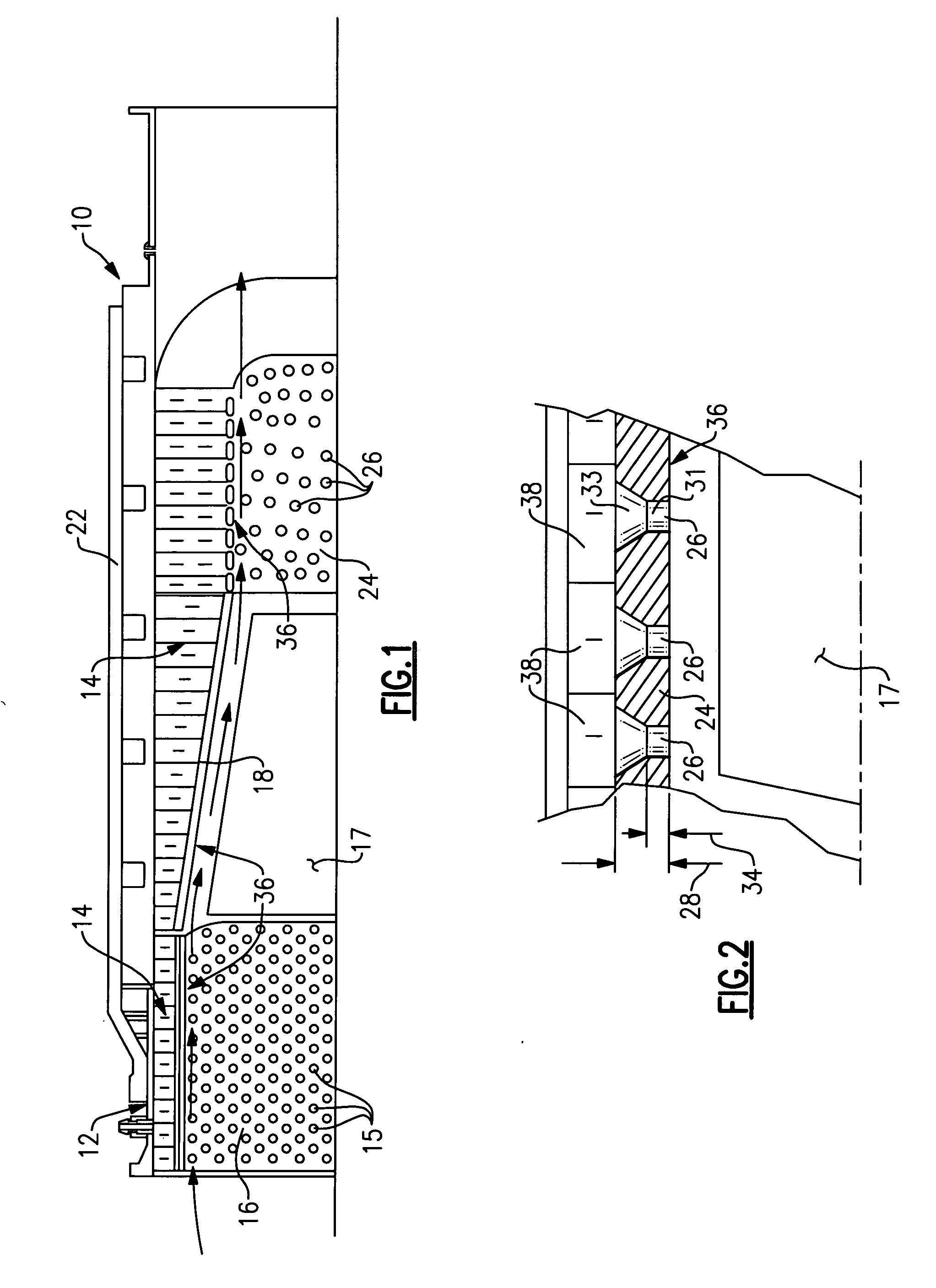
[0016] Referring to FIG. 1 a fan case assembly 10 includes a liner assembly 12. The liner assembly 12 includes a noise attenuation panel 14 for dissipating sound energy generated within the fan case assembly 10. Although this invention is described by way of example for a fan case assembly 10 other duct structures having acoustic treatments will benefit from this disclosure.

[0017] The noise attenuation layer 14 is covered by a flow path wall 36 comprising a perforated face sheet 16 and the acoustic honeycomb noise attenuation panel 14. Flow through the fan case assembly and along the flow path wall 36 begins at a position forward of a fan blade 17. The face sheet 16 is generally forward of a fan blade 17. The abradable strip 18 is orientated rearward of the face sheet 16 in a location adjacent the fan blade 17. Further rearward of the abradable strip 18 and the fan blade 17 is the acoustic panel 24.

[0018] The face sheet 16 includes a plurality of openings 15 that communicate sound...


PUM


Abstract

A liner assembly for a duct includes noise attenuation panel for dissipating sound energy generated within the duct. A damage resistant acoustic panel for installation in high velocity impact prone locations includes a plurality of openings for communicating noise signals to the noise attenuation panel. At lease some of the openings includes a first diameter that extends a depth into the acoustic panel. The depth is no greater than the first diameter. A second portion extends the remainder of the thickness into the acoustic panel and includes a diameter greater than the first diameter. The increased area provided by the second diameter reduces restriction to the transmission of sound energy to the noise attenuation panel within an acoustic panel thickness required for protecting against foreign object damage.

Description

BACKGROUND OF THE INVENTION [0001] This application generally relates to an acoustic liner for a duct. More particularly, this application relates to an acoustic panel for impact prone areas of a duct. [0002] Conventional turbine and turbofan engines for aircraft include a plurality of fan blades that rotate within a duct commonly known as a fan case. The fan case serves as a protective covering to protect the fan blades and the aircraft. Further the fan case channels airflow into the turbine engine. The inner surface of the fan case is constructed to withstand impacts from objects that may come into contact with the fan case and includes acoustical features to reduce the noise emitted from the engine. [0003] The placement of the acoustical features is limited in use to areas of the case that are protected from impact by foreign objects such as shed ice. A noise attenuation layer is covered by a face layer including a plurality of openings. The face layer is typically a thin sheet o...

Claims


Application Information

Patent Timeline
IPC IPC(8): E04H17/00B64F1/26G10K11/00E04B1/82
CPCG10K11/168F05B2260/96
Inventor DEMERS, CHRISTOPHER G.
Owner UNITED TECH CORP
Learn More