Method and apparatus for sputtering onto large flat panels

a flat panel and sputtering technology, applied in the field of material sputtering, can solve the problems of ineffective linear magnetrons, longer deposition periods, and separated magnetrons not being believed to optimally utilize the magnetic fields of constituent magnets, and achieve the effect of increasing uniformity of sputter erosion

Active Publication Date: 2007-01-18
APPLIED MATERIALS INC
View PDF39 Cites 14 Cited by
  • Summary
  • Abstract
  • Description
  • Claims
  • Application Information

AI Technical Summary

Benefits of technology

[0008] One aspect of the invention includes a magnetron having a convolute plasma loop, particularly one having a generally rectangular outline. The loop may be arranged in a serpentine shape having parallel straight portions connected by curved portions or in a rectangularized helical shape having straight portions arranged along orthogonal directions. The plasma loop may be formed between an inner magnetic pole of one magnetic polarity formed in a convolute shape surrounded by an outer pole of the opposed magnetic polarity. Preferably, the inner magnetic pole has a simple folded shape describable as extending along a single path with two ends. The uniformity of the sputter erosion is increased if one or two external ends of the plasma loop are extended in tails extending outwardly of the useful rectangular outline.
[0017] Magnetic uniformity may be improved by using stronger magnets near the center or by placing one or more magnetic shims between the magnets and yoke near the center to bring the center magnets closer to target that the plasma loop is formed by magnets of different strengths or extends over shimmed and unshimmed portions of the magnetron plate.

Problems solved by technology

As a result, for larger panels having minimum dimensions of greater than 1.8 m, linear magnetrons become increasingly ineffective and require longer deposition periods to uniformly sputter the larger targets and coat the larger substrates.
However, there are several disadvantages to this replication approach.
First, the separated magnetrons are not believed to optimally utilize the magnetic fields of the constituent magnets.
Such high voltages are believed to disadvantageously produce excessive particles.
Such high scanning rates require a difficult mechanical design for the much heavier magnetrons covering a substantial fraction of the larger target.
Fourthly, scanning magnetrons including one or more racetrack magnetrons do not completely solve the uniformity problem.
Thus, the target edges are disproportionately eroded, reducing the target utilization and target lifetime, as well as contributing to non-uniform deposition.

Method used


Image

  • Method and apparatus for sputtering onto large flat panels
  • Method and apparatus for sputtering onto large flat panels
  • Method and apparatus for sputtering onto large flat panels

Examples


Embodiment Construction

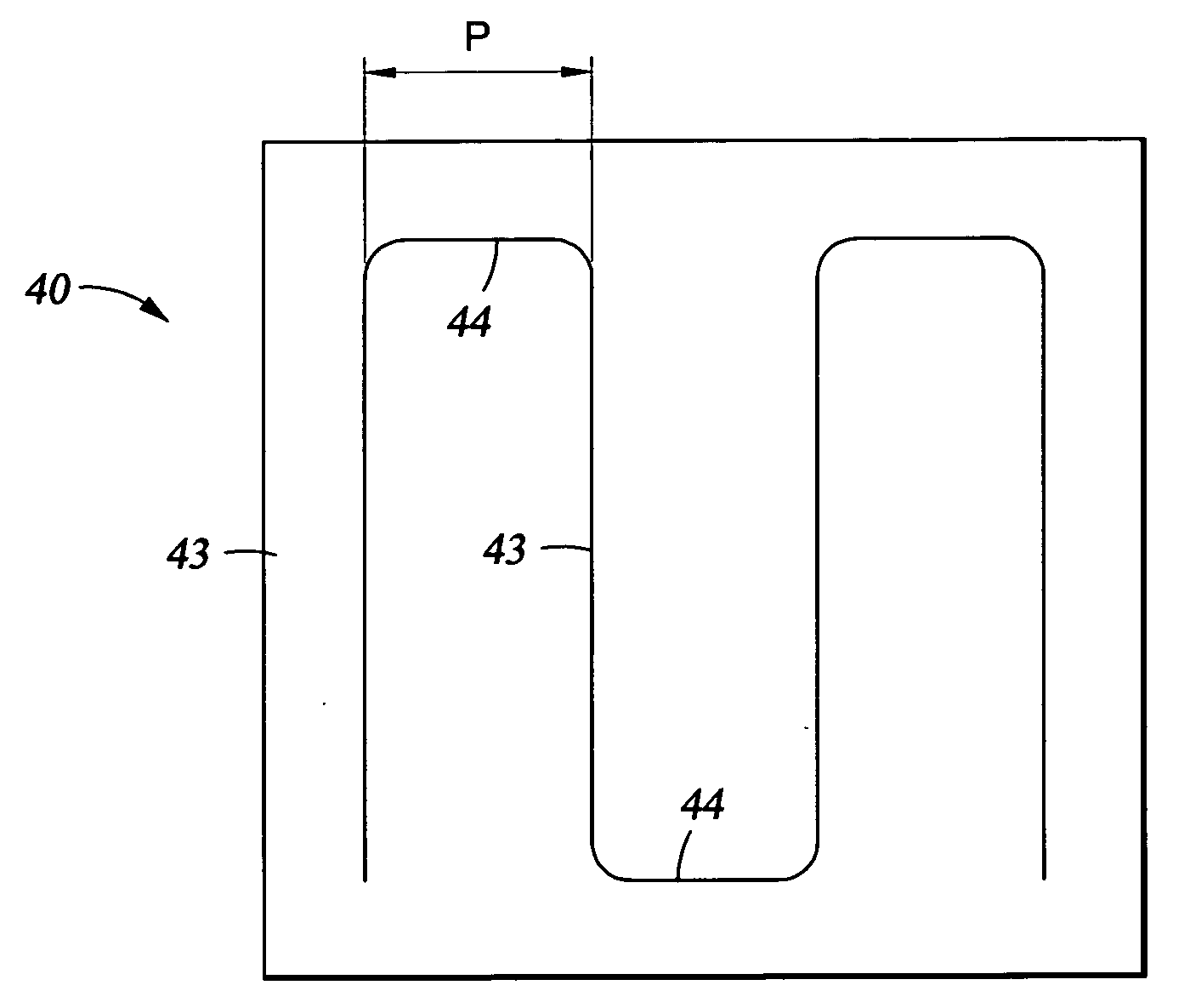
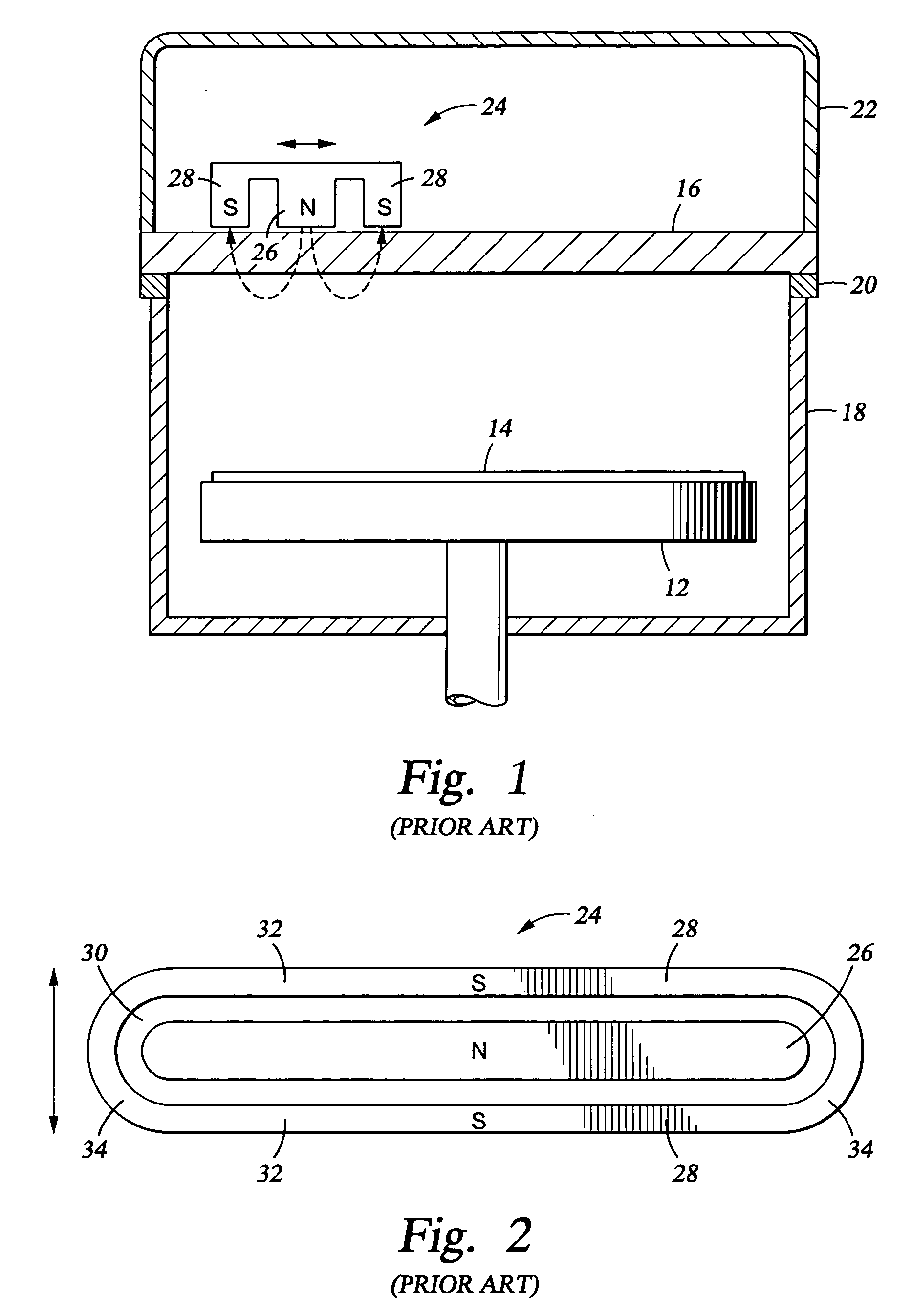
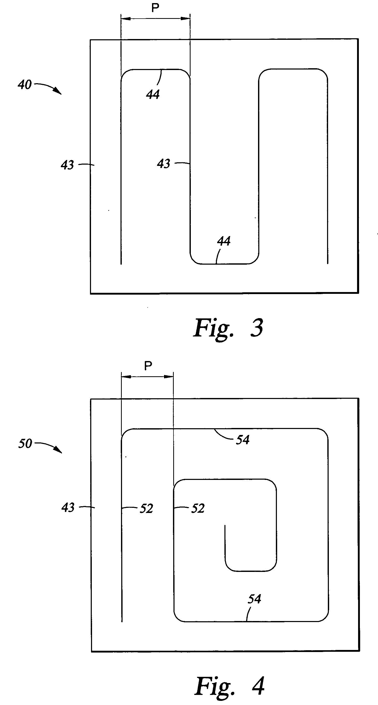
[0058] One aspect of the invention includes shapes for the magnetron that are more convoluted than the linear racetrack of FIG. 2. By convolute is meant a magnetron forming a closed plasma track including curved sections extending in sum over greater than 360° of arc and preferably greater than 720°. In another definition, the linear racetrack magnetron is twisted, for example, into a folded or spiral shape, while it maintains a nearly constant separation of the portions of the gap guiding parallel plasma tracks. In one embodiment illustrated schematically in the plan view of FIG. 3, a serpentine magnetron 40 formed in a magnetron plate 42 includes multiple long parallel straight portions 43 arranged on a pitch P smoothly joined by end portions 44, which may be arc shaped or alternatively short straight portions with curved corners connecting to the straight portions 43. The serpentine magnetron 40 is folded in parallel sections from one lateral side to the other while having substa...


PUM

PropertyMeasurementUnit
sizeaaaaaaaaaa
areaaaaaaaaaaa
sizeaaaaaaaaaa

Abstract

A rectangular magnetron placed at the back of a rectangular sputtering target for coating a rectangular panel and having magnets of opposed polarities arranged to form a gap therebetween corresponding to a plasma track adjacent the target which extends in a closed serpentine or spiral loop. The spiral may have a large number of wraps and the closed loop may be folded before wrapping. The magnetron has a size only somewhat less than that of the target and is scanned in the two perpendicular directions of the target with a scan length of, for example, about 100 mm for a 2 m target corresponding to at least the separation of the gap between parallel portions of the loop. A central ferromagnetic shim beneath some magnets in the loop may compensate for vertical droop. The magnetron may be scanned in two alternating double-Z patterns rotated 90° between them.

Description

RELATED APPLICATIONS [0001] This application is a continuation in part of Ser. No. 11 / 211,141 filed Aug. 24, 2005, which is a continuation in part of Ser. No. 10 / 863,152 filed Jun. 7, 2004, which claims benefit of provisional application 60 / 534,952 filed Jan. 7, 2004. This application also claims benefit of provisional application 60 / 702,327 filed Jul. 25, 2005 and 60 / 705,031 filed Aug. 2, 2005, both incorporated herein by reference.FIELD OF THE INVENTION [0002] The invention relates generally to sputtering of materials. In particular, the invention relates to scanning of the magnetron creating a magnetic field to enhance sputtering from rectangular targets. BACKGROUND ART [0003] Over the past decade, the technology has been intensively developed for fabricating flat panel displays (FPDs), such as used for computer displays and more recently for television screens. Sputtering is the preferred approach in fabricating flat panels for depositing onto large generally rectangular panels ...

Claims


Application Information

Patent Timeline
Patent Type & Authority Applications(United States)
IPC IPC(8): C23C14/00C23C14/32
CPCC23C14/35H01J37/3455H01J37/3408
Inventor LE, HIEN MINH HUUHOSOKAWA, AKIHIROTEPMAN, AVI
Owner APPLIED MATERIALS INC
Why Eureka
Try Eureka