Flexible wiring board and flex-rigid wiring board

a flexible wiring board and rigid technology, applied in the direction of printed circuit manufacturing, printed circuit aspects, non-metallic protective coating applications, etc., can solve the problems of poor adaptability to use, hard flexible sections, and poor folding endurance of printed circuits, so as to improve folding endurance, sacrificing flexibility of flexible printed wiring boards, and excellent breaking strength

Inactive Publication Date: 2007-01-18
SHOWA DENKO KK
View PDF8 Cites 22 Cited by
  • Summary
  • Abstract
  • Description
  • Claims
  • Application Information

AI Technical Summary

Benefits of technology

[0011] According to the present invention, a flex-rigid wiring board comprising an insulating base material, a pattern circuit-forming metal foil layer and an insulating material laminated in that order has a specific construction whereby it is possible to obtain a flex-rig

Problems solved by technology

The pattern circuit-containing metal foil layer sections suffer fatigue wear, resulting in cracks and pattern circuit breaks.
For this reason it has been proposed in the past, for situations requiring repeated folding, to utilize adhesives with high elastic moduli and heat resistance for adhesion between the metal foil layers and insulating base materials in order to prevent generation and propagation of cracks, but the disadvantages of this approach are that the resulting flexible sections are hard and lack flexibility.
When the materials used for construction of the insulating base materials of flex-ri

Method used


Image

  • Flexible wiring board and flex-rigid wiring board
  • Flexible wiring board and flex-rigid wiring board
  • Flexible wiring board and flex-rigid wiring board

Examples


examples

Fabrication and Evaluation of Flexible Wiring Board Test Samples

1) Fabrication of Flexible Wiring Board Test Samples

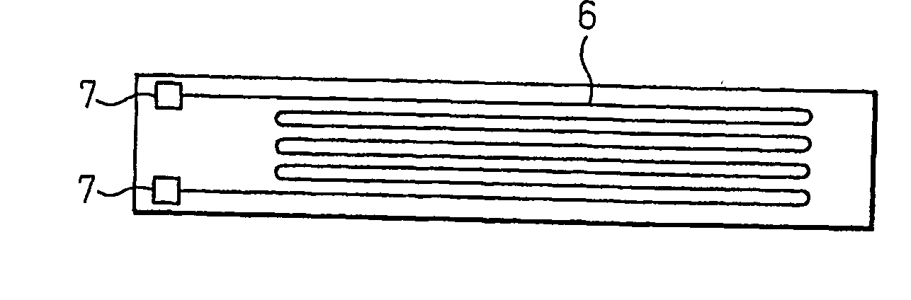
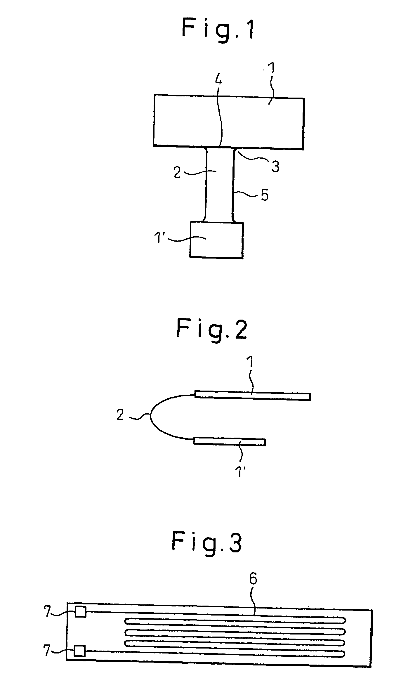
[0090] A flexible wiring board test sample was fabricated for a folding test by the steps described below. FIG. 3 shows schematic diagram of a test sample. The test sample was in a 150 mm×15 mm rectangular shape, and the wiring pattern section was approximately 110 mm×10 mm. The line / space ratio of the wiring pattern section was 0.1 / 0.1 mm, and electrodes were provided at two locations on the edge. A repeating folding test was conducted by repeatedly folding the test sample in the lengthwise direction. Circuit breakage at any point of the wiring during the test interrupted the current flowing between the electrodes and was detectable as a break.

[0091] Step 1:

[0092] After press bonding a dry film resist onto a commercially available copper-clad laminate (R-F775 by Matsushita Electric Works, Ltd., 25 μm-thick polyimide film laminated on one side with 18 μm rolled c...

examples 1 and 2

[0108] The components listed in Table 1 below were used for fabrication of flexible wiring board test samples in the manner described above. The results are shown in Table 1.

TABLE 1Comp.Comp.Example 1Example 2Ex. 1Example 3Ex. 2Example 4Example 5Example 6Example 7Example 8KAYARADpts. by wt.50—505050—503515—ZBR *1KAYARADpts. by wt.—————————50PCR *2Unsaturatedpts. by wt.—50———50————group-containingpolycarboxylic acidresin obtained insynthesis exampleU-200AX *3pts. by wt.555555520405IRGACURE 907 *4pts. by wt.5555555555Silicapts. by wt.8888888888AEROSIL 200pts. by wt.1111111111Dicyandiamidepts. by wt.0.50.50.50.50.50.50.50.50.50.5EPIKOTE YX4000pts. by wt.10101010101010101010Silicone-basedpts. by wt.——————0.50.50.50.5antifoaming agentDiethyleneglycolpts. by wt.20.520.520.520.520.520.520202020monoethyletheracetateTotalpts. by wt.100100100100100100100100100100Glass° C.110921101101101101107027128transitiontemperatureStep 2++−+++++++Step 3++++−+++++Step 4+++−−−++++Flexibility×1000 times168...

examples 3 and 4

[0110] Example 1 was carried out in the same manner, except that Step 4 was eliminated. The results are shown in Table 1.


PUM


Abstract

The invention provides a flexible wiring board for repeated folding sections which exhibits excellent folding endurance, and a flex-rigid wiring board comprising the flexible wiring board as a section thereof. The flexible wiring board for repeated folding sections of the invention comprises a wiring patterned base film layer (11), a flexible insulating material layer (12) covering the layer (11), and a cover film layer (13) covering the layer (12).

Description

CROSS-REFERENCES TO RELATED APPLICATIONS [0001] This application claims benefit under 35 U.S.C. §119(e) to U.S. Provisional Application Ser. No. 60 / 477,959, filed Jun. 13, 2003.TECHNICAL FIELD [0002] The present invention relates to a flexible wiring board for repeated folding sections, and more specifically, it relates to a flex-rigid wiring board provided with a flexible wiring board for repeated folding sections which exhibits excellent folding endurance. BACKGROUND ART [0003] Printed wiring boards having rigid sections formed on portions of wiring patterned flexible printed wiring boards are commonly known as flex-rigid wiring boards (FIG. 1). A flex-rigid wiring board comprises relatively hard rigid sections on which electronic parts are mounted, and foldable (folding) flexible sections for electrical connection between the rigid sections or between the rigid sections and electronic parts. The foldable flexible sections of such flex-rigid wiring boards afford a great deal of fr...

Claims


Application Information

Patent Timeline
IPC IPC(8): H01L23/02H05K1/00H05K3/00H05K3/28
CPCH05K1/0393H05K3/28H05K2201/0195H05K3/4688H05K3/4691H05K3/281
Inventor ISHIGAKI, SATORUNAGASAKA, TARO
Owner SHOWA DENKO KK
Why Eureka
Try Eureka