
Vibration isolation system and method for engine, and control system and method for active vibration isolation support system

a technology of vibration isolation system and support system, which is applied in the direction of machine supports, shock absorbers, jet propulsion mountings, etc., can solve the problem of difficult for the active vibration isolation support system to efficiently exhibit a vibration isolation

Inactive Publication Date: 2007-01-18
HONDA MOTOR CO LTD
View PDF2 Cites 22 Cited by
  • Summary
  • Abstract
  • Description
  • Claims
  • Application Information

AI Technical Summary

Benefits of technology

The present invention relates to an engine vibration isolation system and method for supporting an engine that can switch between a first running and a second running that differ in the number of cylinders that are cut off. The invention aims to accurately estimate the vibration state of the engine during the transition period between the first and second runnings, and to simplify the control of the system during this transition period. The invention provides an active vibration isolation support system that interposes all-cylinder running in a transitional period between the first and second runnings, and a control portion that interposes all-cylinder running when the ratio of the order of vibration of the first and second runnings is not an integer. The all-cylinder running is constant regardless of the magnitude of load of the engine. The invention also provides a control system that sets the start time of one cycle of reading in the engine vibrational state during the cylinder cut-off running so as to coincide with the start time of the cylinder cut-off period, thereby accurately estimating the engine vibrational state.

Problems solved by technology

However, during the transitional period for switching between V4 cylinder cut-off running and L3 cylinder cut-off running, since the waveform of vibration of the engine becomes complicated as described later, there is a problem that it becomes difficult for the active vibration isolation support system to efficiently exhibit a vibration isolation effect.

Method used


Image

  • Vibration isolation system and method for engine, and control system and method for active vibration isolation support system
  • Vibration isolation system and method for engine, and control system and method for active vibration isolation support system
  • Vibration isolation system and method for engine, and control system and method for active vibration isolation support system

Examples


first embodiment

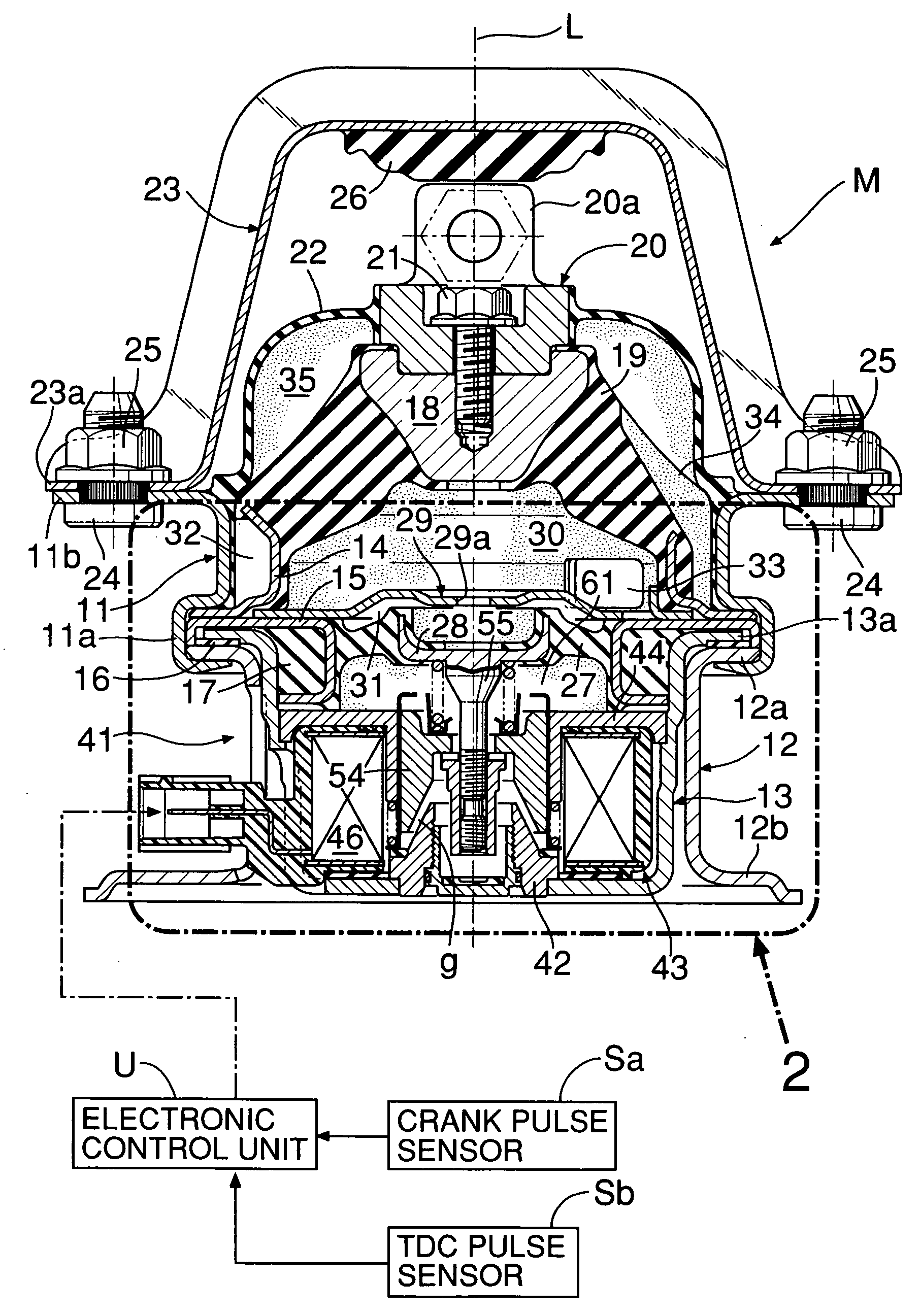
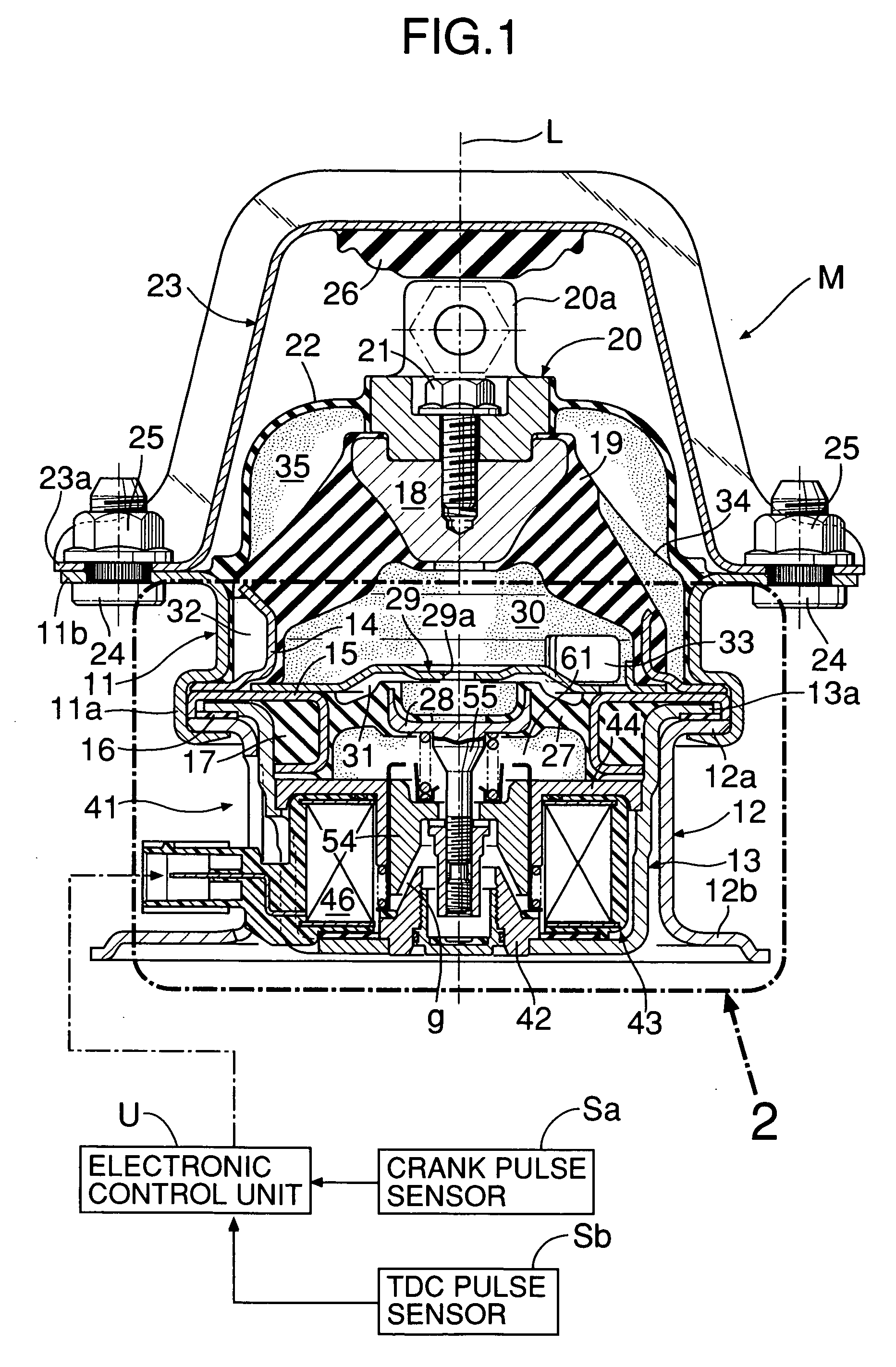
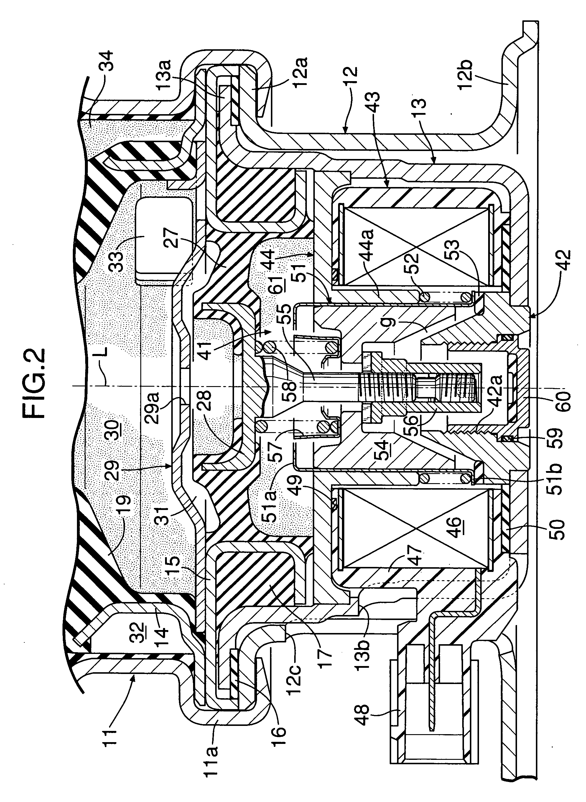
[0036] the present invention is explained below by reference to FIG. 1 to FIG. 9.

[0037] Referring to FIG. 1 and FIG. 2, an active vibration isolation support system M (active control mount) for elastically supporting an automobile engine in a vehicle body frame has a structure that is substantially symmetrical with respect to an axis L, in which, between a flange portion 11a at the lower end of a substantially cylindrical upper housing 11 and a flange portion 12a at the upper end of a substantially cylindrical lower housing 12, a flange portion 13a on the outer periphery of an upwardly opening substantially cup-shaped actuator case 13, an outer peripheral portion of an annular first elastic body support ring 14, and an outer peripheral portion of an annular second elastic body support ring 15 are superimposed and joined by crimping. In this process, an annular first floating rubber 16 is disposed between the flange portion 12a of the lower housing 12 and the flange portion 13a of th...

second embodiment

[0074] the present invention is now explained by reference to FIG. 10 to FIG. 12.

[0075] In V4 cylinder cut-off running, since one cycle of vibration is formed by the combination of one cylinder cut-off period having a crank angle of 120° and two combustion periods having a crank angle of 120°, the engine vibrational state is 1st order vibration (one cycle of vibration in one revolution of the crankshaft), and thus one cycle of the vibration is 360°. Therefore, in V4 cylinder cut-off running, for setting one cycle, there are first to third patterns shown below. Here, ‘comb.’ means combustion, and ‘cut’ means cut-off.

[0076] First pattern: ‘comb.’→‘cut’→‘comb.’

[0077] Second pattern: ‘cut’→‘comb.’→‘comb.’

[0078] Third pattern: ‘comb.’→‘comb.’→‘cut’

[0079] In V6 all-cylinder running and L3 cylinder cut-off running, the combustion intervals of the cylinders are equal to each other. Therefore, the timing to start a read-in period for reading in a vibrational state of the engine is made to c...


PUM


Abstract

When switching between L3 cylinder cut-off running in which a bank on one side of a V6 engine is cut off and V4 cylinder cut-off running in which one cylinder in each of the two banks is cut off, V6 all-cylinder running to operate all the cylinders is interposed therebetween. Therefore, a transitional period is provided between L3 cylinder cut-off running and V6 all-cylinder running and between V6 all-cylinder running and V4 cylinder cut-off running, and no transitional period is present between L3 cylinder cut-off running and V4 cylinder cut-off running. Thus, it is possible to simplify control of an active vibration isolation support system during the transitional period and to avoid deterioration of a vibrational state during the transitional period.

Description

RELATED APPLICATION DATA [0001] The Japanese priority application Nos. 2005-201874 and 2005-203072 upon which the present application is based are hereby incorporated in their entirety herein by reference. BACKGROUND OF INVENTION [0002] 1. Field of the Invention [0003] The present invention relates to an engine vibration isolation system and an engine vibration isolation method for suppressing transmission of vibration to a vehicle body from an engine that can switch between a first running and a second running which differ in the number of cylinders that are cut off, by supporting the engine on the vehicle body via an active vibration isolation support system and controlling via a control portion an actuator of the active vibration isolation support system according to a vibrational state of the engine. [0004] The present invention also relates to a control system and a control method for an active vibration isolation support system for suppressing transmission of vibration to a ve...

Claims


Application Information

Patent Timeline
Patent Type & Authority Applications(United States)
IPC IPC(8): F16F15/00B60K8/00
CPCB60K5/1208F16F15/02F16F13/268
Inventor NEMOTO, HIROTOMIISHIGURO, TETSUYA
Owner HONDA MOTOR CO LTD
Learn More