Light-emitting diode (LED) illumination in display systems using spatial light modulators (SLM)

a technology of spatial light modulator and light-emitting diodes, which is applied in the field of display system system and method, can solve the problems of increasing the complexity increasing the cost and reliability inefficient use of electrical power, so as to improve the dynamic range (bit-depth) of the display system, improve image quality, and improve the performance of the display system.

Inactive Publication Date: 2007-01-18
MARSHALL STEPHEN WESLEY +1
View PDF2 Cites 114 Cited by
  • Summary
  • Abstract
  • Description
  • Claims
  • Application Information

AI Technical Summary

Benefits of technology

[0007] In accordance with a preferred embodiment of the present invention, a method for operating a display system is provided. The method includes computing a set of spectral characteristics, analyzing the set of spectral characteristics, and modulating a light produced by a light source of the display system based upon the analysis. The light source of the display system is capable of rapid switching and is modulatable.
[0008] In accordance with another preferred embodiment of the present invention, a display system is provided. The display system includes a spatial light modulator, with the spatial light modulator being configured to create images made up of pixels by setting each light modulator in an array of light modulators into a state matching a corresponding pixel value, and a rapid switching and modulatable light source (RSMLS) to optically illuminate the spatial light modulator, with the RSMLS being capable of switching at a faster rate than a rate of state switching for the light modulators in the spatial light modulator and producing a light of specifiable intensity and color.
[0009] An advantage of a preferred embodiment of the present invention is that the use of a rapid switching light source (LED) can result in an increase in the dynamic range (bit-depth) of the display system. This can result in a greater number of gray shades and hence, improve image quality. The performance of the display system can also be improved due to more accurate control of bit times.
[0010] A further advantage of a preferred embodiment of the present invention is that the light produced by the LED can be decreased for dark images, which can lead to an increased contrast ratio, which will also result in improved image quality. Furthermore, the ability to decrease the intensity of the light produced by the LED can be achieved without the use of dynamic apertures or neutral density filters, which tend to increase display system complexity and cost.
[0011] Yet another advantage of a preferred embodiment of the present invention is reduced power consumption by reducing light output when the display system is using battery power. This can enable mobile applications with good battery life.

Problems solved by technology

One disadvantage of the prior art is that in addition to being continually on, the light sources will usually be only capable of producing light at a single intensity level.
The addition of the filters and / or apertures can increase display system complexity, which can lead to increased cost as well as decreased reliability.
A second disadvantage of the prior art is that since the light source is always on, even when not needed, there is an inefficient use of electrical power.
This inefficient use of electrical power can preclude the use of batteries to power the display systems that use these light sources, preventing the creation of mobile display systems.
Furthermore, the inability of the light source to turn on and off rapidly can limit a shortest duration of light producible by the display system.
This can place a limit on a number of displayable gray shades (or contrast ratio) and compromise image quality.
Yet another disadvantage of the prior art is that since the intensity of the light source cannot be changed, in situations where dark images are being displayed, light scattered from structures within the SLM can significantly reduce achievable contrast ratio.
This can lead to low quality images, especially for images with a large percentage of dark information.

Method used


Image

  • Light-emitting diode (LED) illumination in display systems using spatial light modulators (SLM)
  • Light-emitting diode (LED) illumination in display systems using spatial light modulators (SLM)
  • Light-emitting diode (LED) illumination in display systems using spatial light modulators (SLM)

Examples


Embodiment Construction

[0020] The making and using of the presently preferred embodiments are discussed in detail below. It should be appreciated, however, that the present invention provides many applicable inventive concepts that can be embodied in a wide variety of specific contexts. The specific embodiments discussed are merely illustrative of specific ways to make and use the invention, and do not limit the scope of the invention.

[0021] The present invention will be described with respect to preferred embodiments in a specific context, namely an SLM display system making use of digital micromirror devices as light modulators. The invention may also be applied, however, to other SLM display systems, such as those making use of LCD, LCoS, deformable mirrors, and so forth.

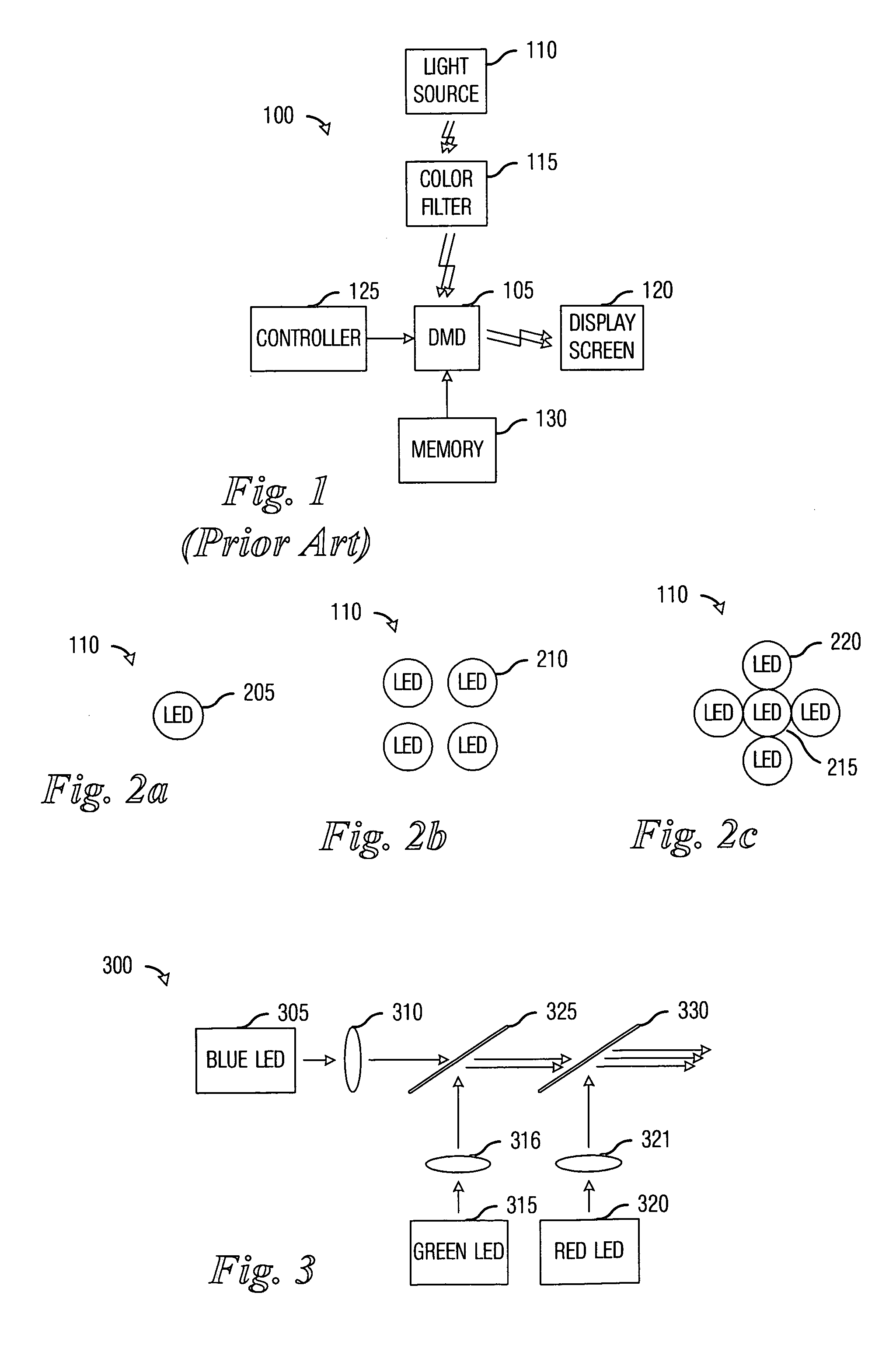
[0022] With reference now to FIG. 1, there is shown a diagram of a prior art display system 100. The display system 100 features a digital micromirror device (DMD) 105 as a light modulator. The DMD 105 comprises an array of positiona...


PUM


Abstract

System and method for enhancing performance in an SLM display system using LED illumination. A preferred embodiment comprises computing a set of spectral characteristics, analyzing the set of spectral characteristics, and modulating a light produced by a light source of a display system based upon the analysis, wherein the light source comprises one or more light-emitting diodes. The spectral characteristics can provide information regarding either the images being displayed by the display system or an operating environment of the display system. Either can have an impact upon the quality of the images being displayed on the display system and can be used to make adjustments to the light source.

Description

TECHNICAL FIELD [0001] The present invention relates generally to a system and method for display systems, and more particularly to a system and method for enhancing performance in an SLM display system using LED illumination. BACKGROUND [0002] Display systems using spatial light modulators (SLM), such as digital micromirror devices (DMD), liquid crystal display (LCD), liquid crystal on silicon (LCoS), deformable mirrors, and so forth, typically use light sources that are continually on to display an image (or a sequence of images) on a display screen. These light sources normally are turned on when the display system is powered on and remain on until the display system is turned off due to their slow on-off cycle times. The light sources, such as ultra-high-pressure (UHP) arc lamps, have a broadband visible light spectrum and require the use of color filters to selectively transmit desired color sequences to the SLM. These light sources can be extremely bright and can have long lif...

Claims


Application Information

Patent Timeline
Patent Type & Authority Applications(United States)
IPC IPC(8): G03B21/14
CPCH04N9/312G03B21/2033H04N9/3197H04N9/3155
Inventor MARSHALL, STEPHEN WESLEYPENN, STEVEN MONROE
Owner MARSHALL STEPHEN WESLEY
Why Eureka
Try Eureka