
Flexible cube-corner retroreflective sheeting

a cube-corner and retroreflective technology, applied in the field of flexible cube-corner retroreflective sheeting, can solve the problems of not being able to disclose the combination of higher elastic modulus cubes and low elastic modulus body layers, and achieve extraordinary dimensional stability during flexing, good retroreflective performance, and high flexibility

Inactive Publication Date: 2007-01-18
3M INNOVATIVE PROPERTIES CO
View PDF54 Cites 21 Cited by
  • Summary
  • Abstract
  • Description
  • Claims
  • Application Information

AI Technical Summary

Benefits of technology

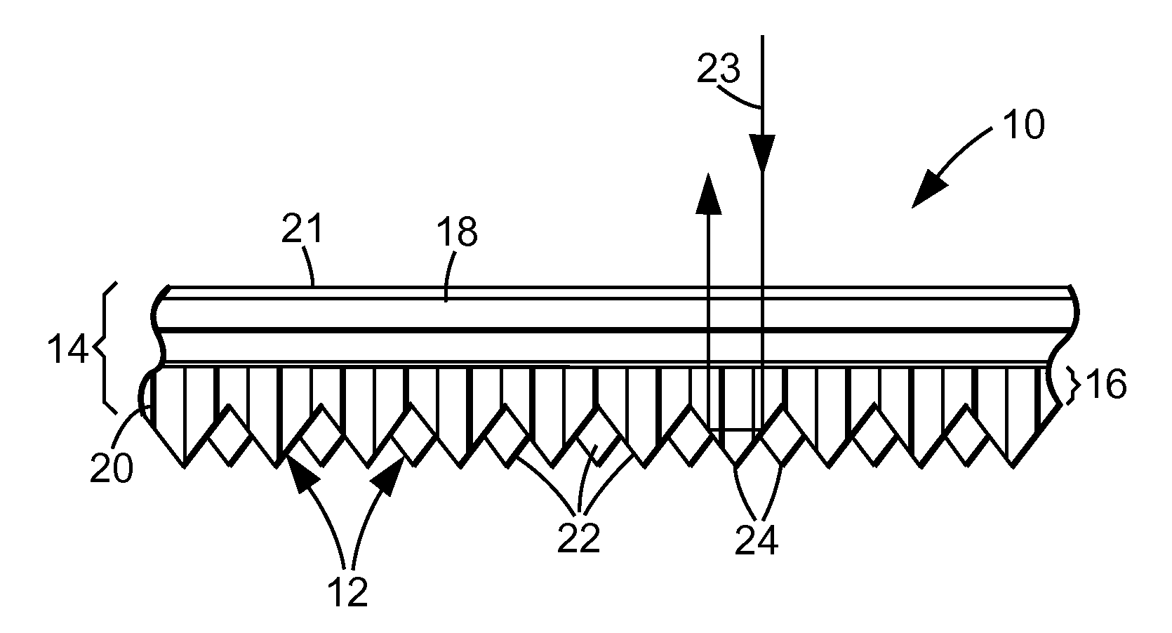
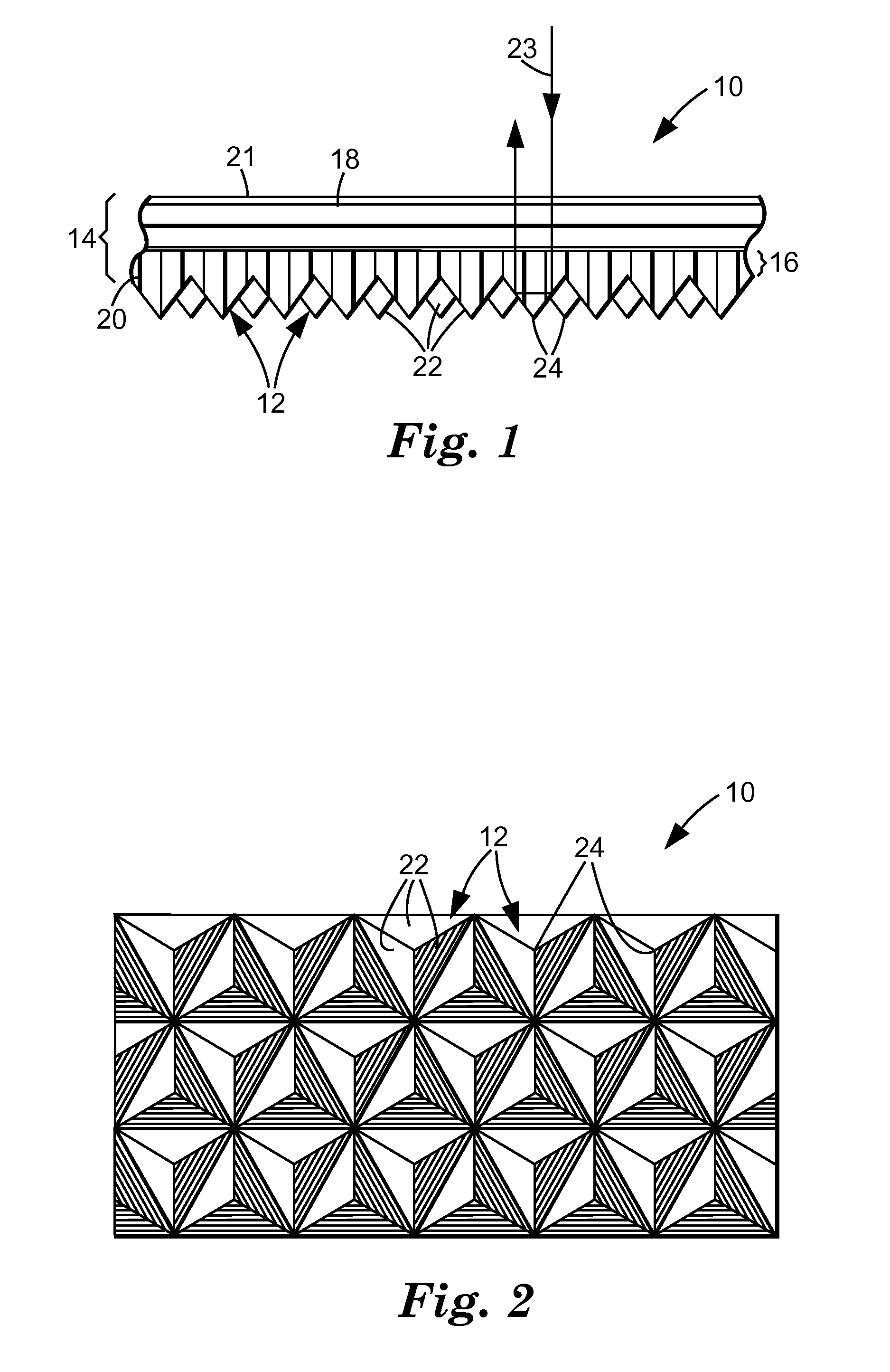
[0016] As indicated above, retroreflective sheetings that employ different polymers in the cubes and body portion of the sheeting are known, see, for example, U.S. Pat. Nos. 5,117,304 and 3,684,348. It is believed, however, that no document discloses the combination of higher elastic modulus cubes and a low elastic modulus body layer. This combination is very advantageous because the sheeting can be highly flexed without suffering from a substantial loss of retroreflectivity. The flexibility demonstrated by sheetings of the invention is great enough to allow the sheeting to be adhered to a highly conformed surface (for example, over a protruding rivet) by use of a conventional pressure sensitive adhesive. The cube-corner elements demonstrate extraordinary dimensional stability during flexing and thereby provide good retroreflective performance when conformed. The dimensional stability and good retroreflective performance can be maintained at high temperatures.

Problems solved by technology

It is believed, however, that no document discloses the combination of higher elastic modulus cubes and a low elastic modulus body layer.

Method used


Image

  • Flexible cube-corner retroreflective sheeting
  • Flexible cube-corner retroreflective sheeting
  • Flexible cube-corner retroreflective sheeting

Examples


example 2

[0060] A second sample was produced by the procedure outlined in Example 1, except the body layer was a previously extruded 79 micrometer (0.0031 inch) thick, continuous, poly(ethylene-co-acrylic acid) film (Primacor™ 3440, material supplied by The Dow Chemical Company, Midland, Mich.). An aliphatic polyester urethane primer was applied to promote adhesion of this film to the poly(carbonate) surface. The primer (Q-Thane™ QC-4820, supplied by K.J. Quinn and Co., Inc., Seabrook, N.H., was solvent coated to form a layer having a final dried thickness of approximately 2.5 micrometers (0.0001 inch).

example 3

[0061] A third sample was produced by the procedure outlined in Example 1, except the body layer was a previously extruded 71 micrometer (0.0028 inch) thick aliphatic polyester urethane body layer (Morthane™ PNO3, supplied by Morton International, Seabrook, N.H.).

[0062] Table 1 summarizes the elastic modulus of the body layer material for the laminate samples evaluated in Examples 1-3. Elastic modulus was determined according to ASTM D882-75b using a Sintech 1 static weighing constant rate-of-grip separation tester, produced by MTS Systems Corp, Eden Prairie, Minn. Elastic modulus for the poly(carbonate) used in the cubes and land layer for all samples was 20.0×10⁸ pascals (29.1×10⁴ psi).

TABLE 1ExampleBody LayerNumberMaterialElastic Modulus1polymethylmethacrylate24.4 × 108 pascal(35.4 × 10⁴ psi)2poly(ethylene-co-acrylic acid)1.24 × 10⁸ pascal(1.80 × 10⁴ psi)3aliphatic polyester urethane0.34 × 108 pascal(0.50 × 10⁴ psi)

[0063] The samples of Examples 1-3 were tested for apparent be...


PUM

PropertyMeasurementUnit
elastic modulusaaaaaaaaaa
thicknessaaaaaaaaaa

Abstract

A retroreflective article 10 has a body portion 14 and a multitude of cube-corner elements 12 that project from a rear side 20 of the body portion 14. The body portion 14 includes a body layer 18 that contains a light-transmissible polymeric material having an elastic modulus less than 7×10⁸ pascals. The cube-corner elements 12 contain a light transmissible polymeric material having an elastic modulus greater than 16×108 pascals. A retroreflective article of this construction can be highly flexed while maintaining good retroreflective performance.

Description

[0001] This application is a continuation of U.S. application Ser. No. 10 / 039,103, filed Jan. 4, 2002, which is a continuation of U.S. application Ser. No. 08 / 516,018, filed Aug. 16, 1995, issued as U.S. Pat. No. 6,350,035, which is a continuation of U.S. application Ser. No. 08 / 139,433, filed Oct. 20, 1993, issued as U.S. Pat. No. 5,450,235, the disclosures of which are hereby incorporated by reference.TECHNICAL FIELD [0002] This invention pertains to a flexible cube-corner retroreflective sheeting, and more particularly to a flexible cube-corner retroreflective sheeting that uses a high elastic modulus polymer in the cube-corner elements and a low elastic modulus polymer in the body portion. BACKGROUND OF THE INVENTION [0003] Retroreflective sheetings have the ability to redirect incident light towards its originating source. This unique ability has led to the wide-spread use of retroreflective sheetings on a variety of articles. Very often the retroreflective sheetings are used o...

Claims


Application Information

Patent Timeline
Patent Type & Authority Applications(United States)
IPC IPC(8): G02B5/124B29C39/14B32B3/30
CPCB29C39/148G02B5/124Y10S359/90Y10T428/24479Y10T428/254Y10T428/25Y10T428/24521Y10T428/252
Inventor SMITH, KENNETH L.HUANG, TZU-LI J.CODERRE, JAMES C.
Owner 3M INNOVATIVE PROPERTIES CO
Learn More