Optical pickup apparatus for optical disc
a technology of optical discs and pickup apparatuses, applied in the direction of mountings, instruments, data recording, etc., can solve the problems of apparatuses that cannot be precisely corrected, and inability etc., to achieve excellent light spots.
- Summary
- Abstract
- Description
- Claims
- Application Information
AI Technical Summary
Benefits of technology
Problems solved by technology
Method used
Image
Examples
first embodiment
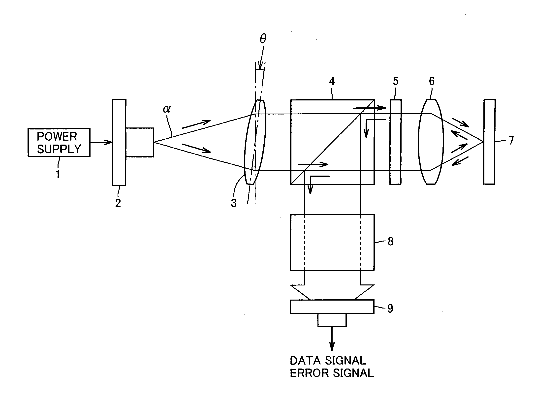
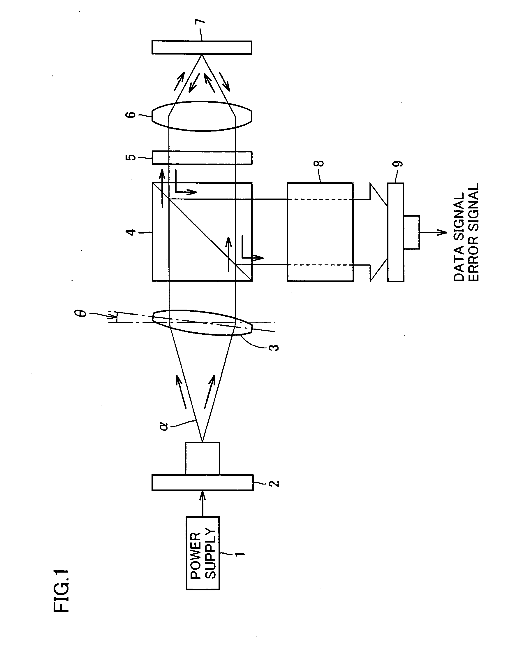
[0028]FIG. 1 shows an overall configuration of an optical pickup apparatus according to one embodiment of the present invention, and FIG. 2 shows a substantial part thereof Referring to FIGS. 1 and 2, the optical pickup apparatus includes a semiconductor laser element 2 such as a laser diode connected to a power supply 1. Laser diffusion light a emitted from semiconductor laser element 2 is converted into parallel light by a collimator lens 3.
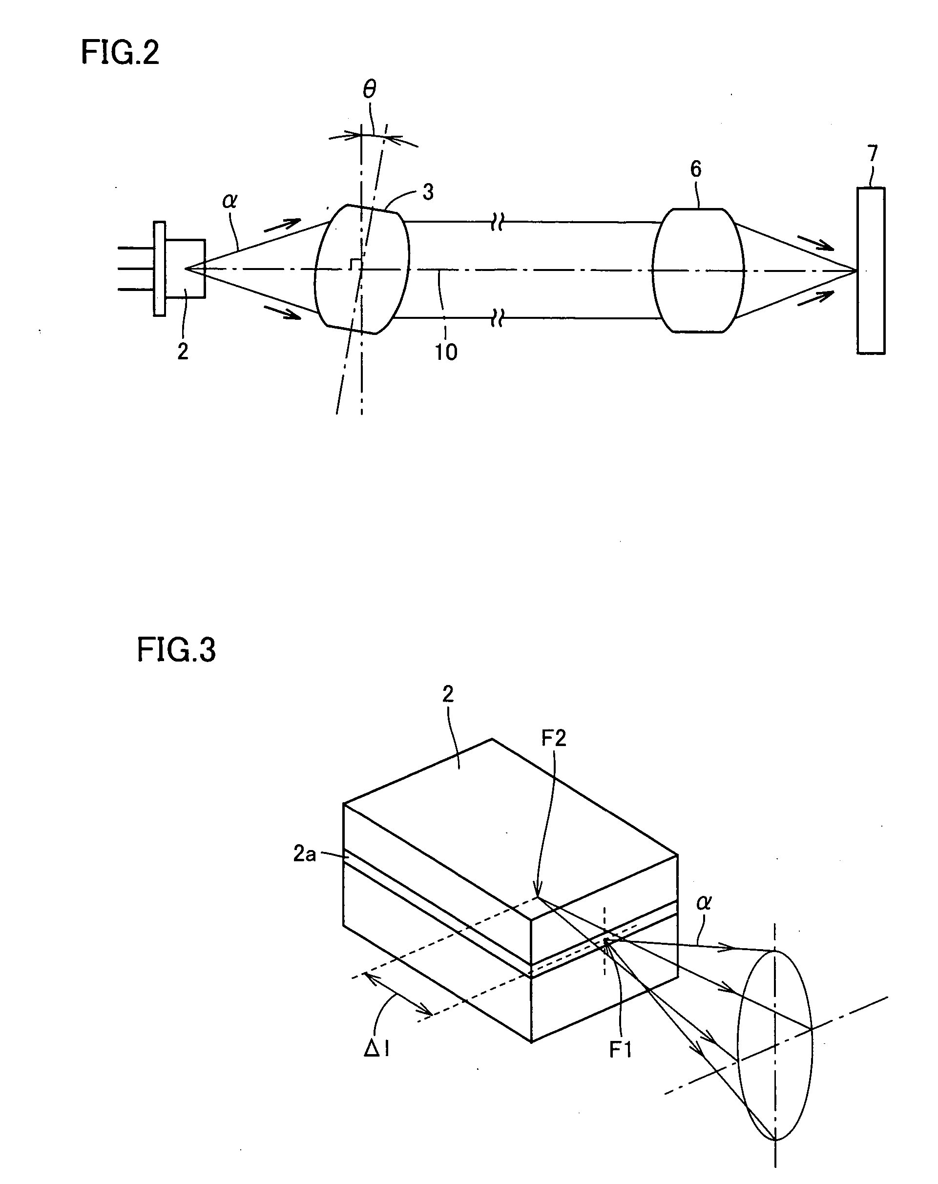
[0029] Here, semiconductor laser element 2 necessarily has an astigmatic difference due to its characteristics, which necessarily causes astigmatism on the focus plane of the laser light. FIG. 3 is an illustration for describing an astigmatic difference of semiconductor laser element 2. An active layer 2a generating laser diffusion light a of semiconductor laser element 2 has a small thickness and formed in a rectangular shape, whereby the focus position of laser diffusion light α varies on an optical axis between perpendicular and parallel di...
second embodiment
[0042]FIGS. 11A and 11B are perspective views showing a structure of a collimator lens 3 and an optical base 25 of an optical pickup apparatus according to a second embodiment of the present invention. FIG. 12A is a plan view showing a structure of optical base 25, and FIG. 12B is a cross-sectional view along XIIB-XIIB line in FIG. 12A.
[0043] Optical base 25 is different from optical base 11 of the first embodiment in that three protruding portions 16, 17 and 19 are removed.
[0044] Specifically, a reference surface 14 is formed at the bottom of groove 12 on an upstream side (left side in FIG. 12A) relative to line L2 that is perpendicular to the center line of through hole 13 (that is, optical axis 10) and extends in the width direction of groove 12. A tilt surface 15 is formed at the bottom of groove 12 on a downstream side (right side in FIG. 12A) relative to line L2. Tilt surface 15 is lower on the downstream side than on the upstream side. In other words, reference surface 14 a...
third embodiment
[0050]FIGS. 15A-15C are graphs indicative of the relationship between angles θx, θy formed by collimator lens 3 and optical axis 10 and astigmatism. Here, θx is an angle of collimator lens 3 with reference to the direction perpendicular to optical axis 10 when collimator lens 3 is tilted rotating about line L2 in FIG. 12A. θy is, as shown in FIGS. 16A and 16B, an angle of collimator lens 3 with reference to the direction perpendicular to optical axis 10 when collimator lens 3 is tilted rotating about a line L3 perpendicular to line L2 in FIG. 12A and optical axis 10.
[0051] In a state where an astigmatic distance of a semiconductor laser element 2 is 0, when tilt angle θx of collimator lens 3 rotating about line L2 in FIG. 12A is changed, astigmatism by the tilt arrangement of collimator lens 3 takes on the maximum value of 0 when θx=0, as shown by a solid curve 30 in FIG. 15A. Increasing θx positively or negatively, astigmatism increases negatively.
[0052] Now, it is assumed that t...
PUM
| Property | Measurement | Unit |
|---|---|---|
| angle | aaaaa | aaaaa |
| tilt angle | aaaaa | aaaaa |
| angle | aaaaa | aaaaa |
Abstract
Description
Claims
Application Information
 - R&D
- Intellectual Property
- Life Sciences
- Materials
- Tech Scout
- Unparalleled Data Quality
- Higher Quality Content
- 60% Fewer Hallucinations
Browse by: Latest US Patents, China's latest patents, Technical Efficacy Thesaurus, Application Domain, Technology Topic, Popular Technical Reports.
© 2025 PatSnap. All rights reserved.Legal|Privacy policy|Modern Slavery Act Transparency Statement|Sitemap|About US| Contact US: help@patsnap.com


