

Parallel Tomlinson-Harashima precoders
- Summary
- Abstract
- Description
- Claims
- Application Information
AI Technical Summary
Problems solved by technology
Method used
Image

Examples
Embodiment Construction
Background on Tomlinson-Harashima Precoding
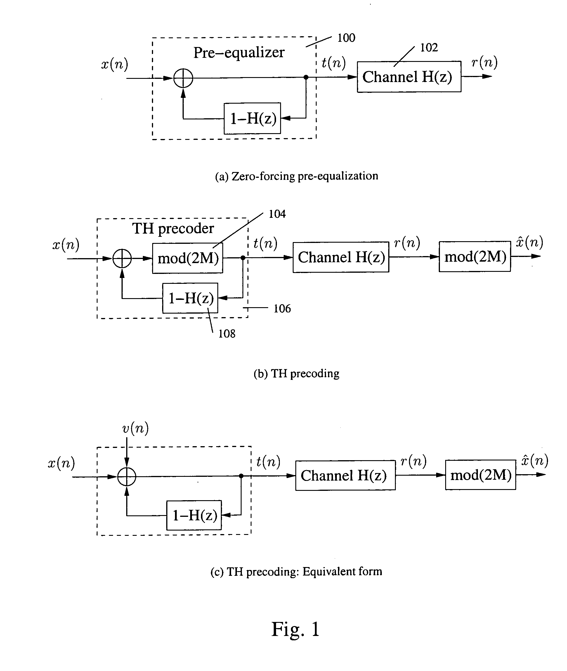
[0021] Consider a discrete-time channel H(z)=1+∑i=1LHhiz-i,EQ. (1)
where LH is the channel memory length. We assume that the model is known at the transmitter side. We also assume that the transmitted symbols are PAM-M symbols, where the symbol set is {±1, ±3, . . . , ±(M−1)}. To remove inter-symbol interference (ISI), we can use zero-forcing pre-equalization, which basically implements the inverse of the channel transfer function at the transmitter side, as illustrated in FIG. 1(a). However, one problem associated with the scheme in FIG. 1(a) is that the output of the pre-equalizer has a large dynamic range, which may even be unlimited.
[0022] Tomlinson and Harashima (See, M. Tomlinson, “New automatic equalizer employing modulo arithmetic,”Electron. Lett., vol. 7, pp. 138-139, March 1971; and H. Harashima and H. Miyakawa, “Matched-transmission technique for channels with intersymbol interference,”IEEE Trans. Commun., vol. 20, pp. 774...
PUM
 Abstract
Description
Claims
Application Information