Coordinated data flow control and buffer sharing in umts

a data flow control and buffer sharing technology, applied in data switching networks, store-and-forward switching systems, wireless communication, etc., can solve the problems of inability to send allocation frames too frequently, inability to use ub /sub>interfaces which are expensive to use, and inability to reduce memory requirements for node-b, improve communication reliability, and reduce memory requirements

Inactive Publication Date: 2007-01-18
TELEFON AB LM ERICSSON (PUBL)
View PDF10 Cites 38 Cited by
  • Summary
  • Abstract
  • Description
  • Claims
  • Application Information

AI Technical Summary

Benefits of technology

[0036] One of the main advantages of the invention is that the Node-B's buffer level depends only on the amount of scheduled data, that is data scheduled for transmission from Node-B to the respective UEs, instead of the number of packet data streams that traverses through the node. This means that the main buffering of user data can be sustained in SRNC, which in turn implies (1) reduced memory requirements for Node-B, (2) increased communication reliability, (3) improved robustness against error events that are caused by hand-offs, (4) smoothened traffic over the Iub and Iur interfaces, and (5) reduced amount of MAC-d PDUs transmitted from SRNC but not yet received at Node-B. Since transmissions are from SRNC are very slow it is important to keep the number of transmitted but not yet received MAC-d PDUs as low as possible.

Problems solved by technology

A problem arises if Node-B contains too much data.
This is so, because UEs are occasionally handed off from one Node-B to another whereas the frame protocol cannot transport data between different Node-Bs.
This is not feasible, because this would require extensive use of the Iub interface which is expensive to use.
It is thus not possible to send the allocation frames too frequently.
Buffer capacity in Node-B is generally expensive.
If the buffers are too large, then Node-B will be expensive.
It is not an easy task to expand the total buffer capacity in Node-B by adding new memory resources, because Node-B is often mounted in towers, masts, roofs etc.
The problem therefore boils down to keeping the amount of buffered data in Node-B as low as possible without negatively influencing the quantity of flowing data.
This problem in its turn can be broken down in two problems: efficient flow control and efficient memory handling.
This is so, because it is impossible to predict which UE's buffer the scheduler will select for transmission.
If under these circumstances a UE is switched from one Node-B to new Node-B in a handover procedure there is no mechanism available to transfer the data already buffered in Node-B to the new Node-B and the buffered data is lost.
Retransmission from SRNC is a slow and expensive procedure since it takes place over the UTRAN interfaces.
These are slow and typically traverse several network nodes.
A problem arises since the above-described flow control method handles separate packet data streams independently of each other and the amount of data buffered in Node-B is lowered only for a given UE.
Although the buffer level for a separate individual data stream can be lowered the total amount of buffered data can be therefore excessive for a large user population.
Accordingly the problem remains, data must be retransmitted from SRNC to Node-B when a user, other than those that had their buffer levels reduced, is moved from one Node-B to another (handover).

Method used


Image

  • Coordinated data flow control and buffer sharing in umts
  • Coordinated data flow control and buffer sharing in umts
  • Coordinated data flow control and buffer sharing in umts

Examples


example 1

[0068] Refer to FIG. 6. Suppose the SRNC buffer has 100 MAC-d PDUs pending for transmission to a single user's buffer in Node-B. Suppose also that this single user's buffer has a total buffer capacity of 90 MAC-d PDUs and that, at the reception of the buffer request frame, 10 MAC-d PDUs are currently buffered in Node-B. Suppose also that Node-B, at three previous instants, has given SRNC 10, 20, and 30 credits (expressed in MAC-d PDU units). These 60 MAC-d PDUs are thus outstanding credits and the corresponding MAC-d PDUs have not yet been received by Node-B (for example due to delay in the transmission). The state of the single user's buffer in SRNC and in Node-B is illustrated at the top of the figure.

[0069] The arrow marked CAPREQ 100 represents step 1 in the per flow based flow control process and the arrow apex represents step 2. Step 3 is illustrated at the Node-B buffer. Of the total buffer space (90 MAC-d PDUs) 10 are occupied, leaving room for 80 MAC-d PDUs. Applying step ...

example 2

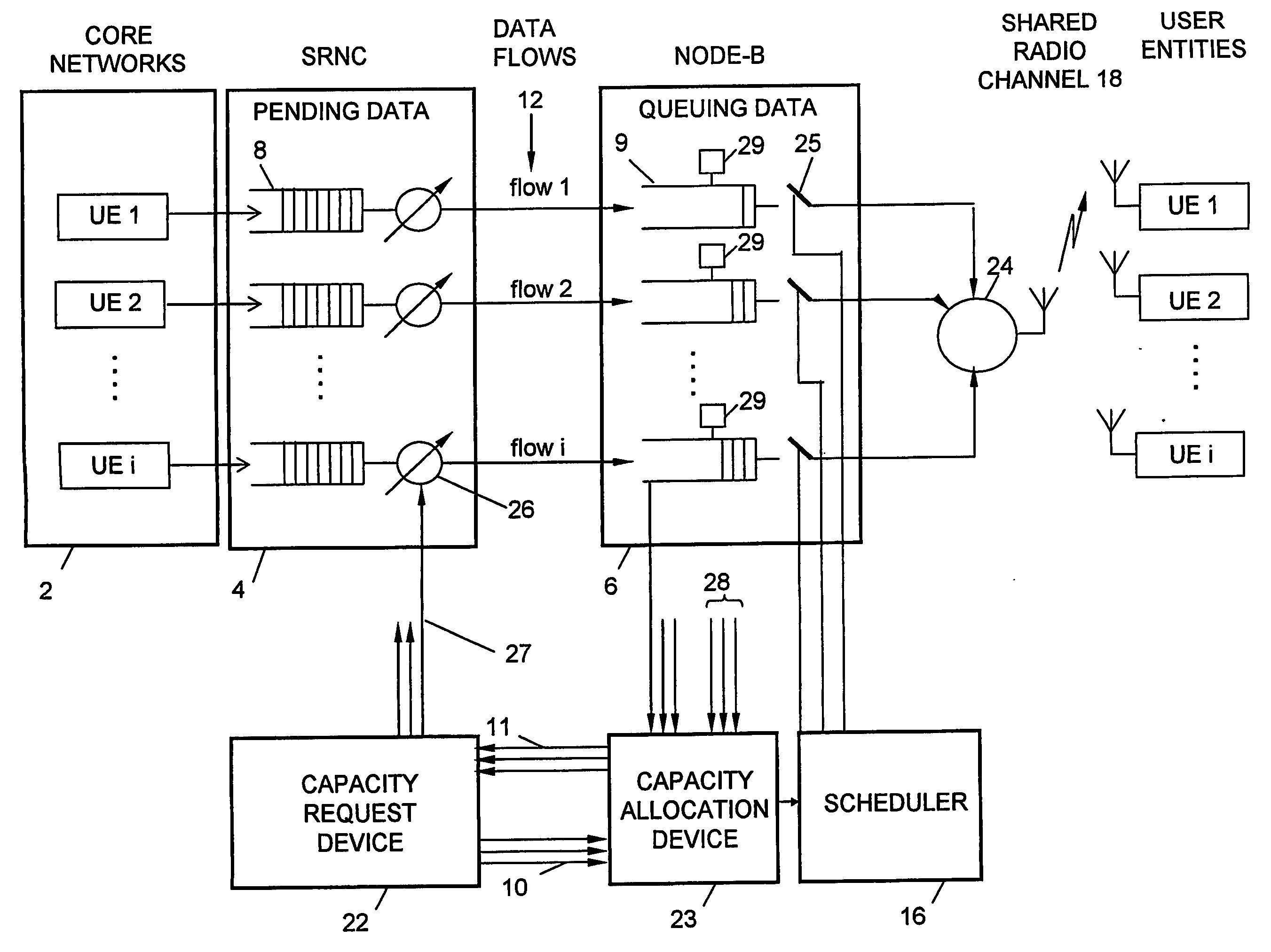
[0092] Refer to FIG. 7. Assume there are three UEs, each one having a respective buffer in Node-B as is indicated by the broken horizontal lines through Node-Bs buffer. Generally the same assumptions as made in Example 1 apply. The buffers in Node-B are filled to various individual levels. Adding these together indicates that Node-Bs buffer is filled with 10 MAC-d PDUs as in Example 1. Assume also that SRNC has different amounts of user data to send to the three UEs. If these amounts are added SRNC has a total of 100 MAC-d PDUs to send to the three UEs like in Example 1. The total memory space of the buffers in Node-B is, like in Example 1, 90 MAC-d PDUs. Finally it is assumed that UE1 and UE2 both have reported a channel quality indicator QI=0.8 indicating a good channel, while UE3 has reported a QI=0.4 indicating a less good channel. Also, the assumption in Example 1 apply, indicating that Node-B has a total predefined target level of 90 MAC-d PDUs.

[0093] Following steps 1-4iii i...


PUM


Abstract

The invention describes a flow control method to control HS-DSCH data streams over UTRAN Iub and Iur interfaces. Two credit assignment schemes are also described. A radio network node at which the flow control method executes is proposed. Finally a computer program product for execution of the flow control method and the credit assignment schemes is described. The control of separate user data flows is coordinated by Node-B and data transport over the Iub and Iur interfaces is adapted to data transfer over the Uu interface. The main advantage is that buffering can be primarily maintained in SRNC. It is shown that the proposed flow control method can significantly reduce Node-B's buffer level when compared to a scheme where the control of individual data flows is performed independently of each other. It is also shown that the negative impact on the quantity of flowing data is generally minor.

Description

TECHNICAL FIELD OF THE INVENTION [0001] This invention relates to a system and method for sharing scarce buffering resources between several users in a universal mobile telecommunication system (UMTS). DESCRIPTION OF RELATED ART [0002] Multimedia wireless networks are undergoing rapid expansion with the increase in demand for Internet like services such as web browsing, dynamic sharing of resources and streaming audio and video. Such wireless networks can either be mobile or fixed. Mobile networks of this type are known as third generation (3G) mobile communication systems. Unlike previous types of mobile networks that carried mainly circuit switched voice traffic from PSTN (Public Switched Telephone networks) 3G networks will carry various packet data from a variety of networks, including PSTN, B-ISDN, PLMN and Internet. [0003] There is an ongoing process of standardising a set of protocols collectively known as the Universal Mobile Telecommunications Systems (UMTS). FIG. 1 illustr...

Claims


Application Information

Patent Timeline
Patent Type & Authority Applications(United States)
IPC IPC(8): H04Q7/20H04B7/00H04L12/54H04W28/10H04W28/14H04W72/04
CPCH04L12/5695H04L47/15H04L47/822H04W72/04H04L47/825H04W28/10H04W28/14H04L47/824H04L47/83H04L47/70
Inventor BEMING, PERSUNELL, KAI-ERIKJOHANSSON, NIKLAS
Owner TELEFON AB LM ERICSSON (PUBL)
Why Eureka
Try Eureka