Method of designing golf club and golf club head

a golf club and design method technology, applied in the field of golf clubs and golf club heads, can solve the problems of insufficient restitution performance, excessive rigidity of the face part, low strength of the wood head, etc., and achieve the effect of reducing the cost and the time required to execute computations, reducing the size of the sweet area, and easy design

Inactive Publication Date: 2007-01-18
DUNLOP SPORTS CO LTD
View PDF22 Cites 86 Cited by
  • Summary
  • Abstract
  • Description
  • Claims
  • Application Information

AI Technical Summary

Benefits of technology

[0060] As described above, according to the method of the present invention for designing the golf club head carried out by using the golf club head model and the golf ball model, simulation is executed in an imaginary space by using a computer to set the maximum value of the Mises stresses generated by the collision between the golf ball model and the golf club head model at any off-center positions of the front surface of the face part thereof to less than 1.3 times the maximum value of the Mises stress generated by the collision between the golf ball model and the golf club head model at the center of the front surface of the face part thereof. To do so, the positions of the reinforcing ribs and the configurations thereof including the sectional areas and the heights are changed. That is, the designing method of the present invention allows the golf club head to be designed very easily without performing steps of making actual golf club heads on an

Problems solved by technology

However, thinning the face part causes the strength of the wood head to be low.
Because all the reinforcing ribs extend vertically in the golf club head disclosed in the patent document 1, the reinforcing ribs disposed at the toe and the heel make the rigidity of the face part excessively high.
Thus at the time of collision between a golf ball and the face part, the face part is excessively restrained from

Method used


Image

  • Method of designing golf club and golf club head
  • Method of designing golf club and golf club head
  • Method of designing golf club and golf club head

Examples


examples

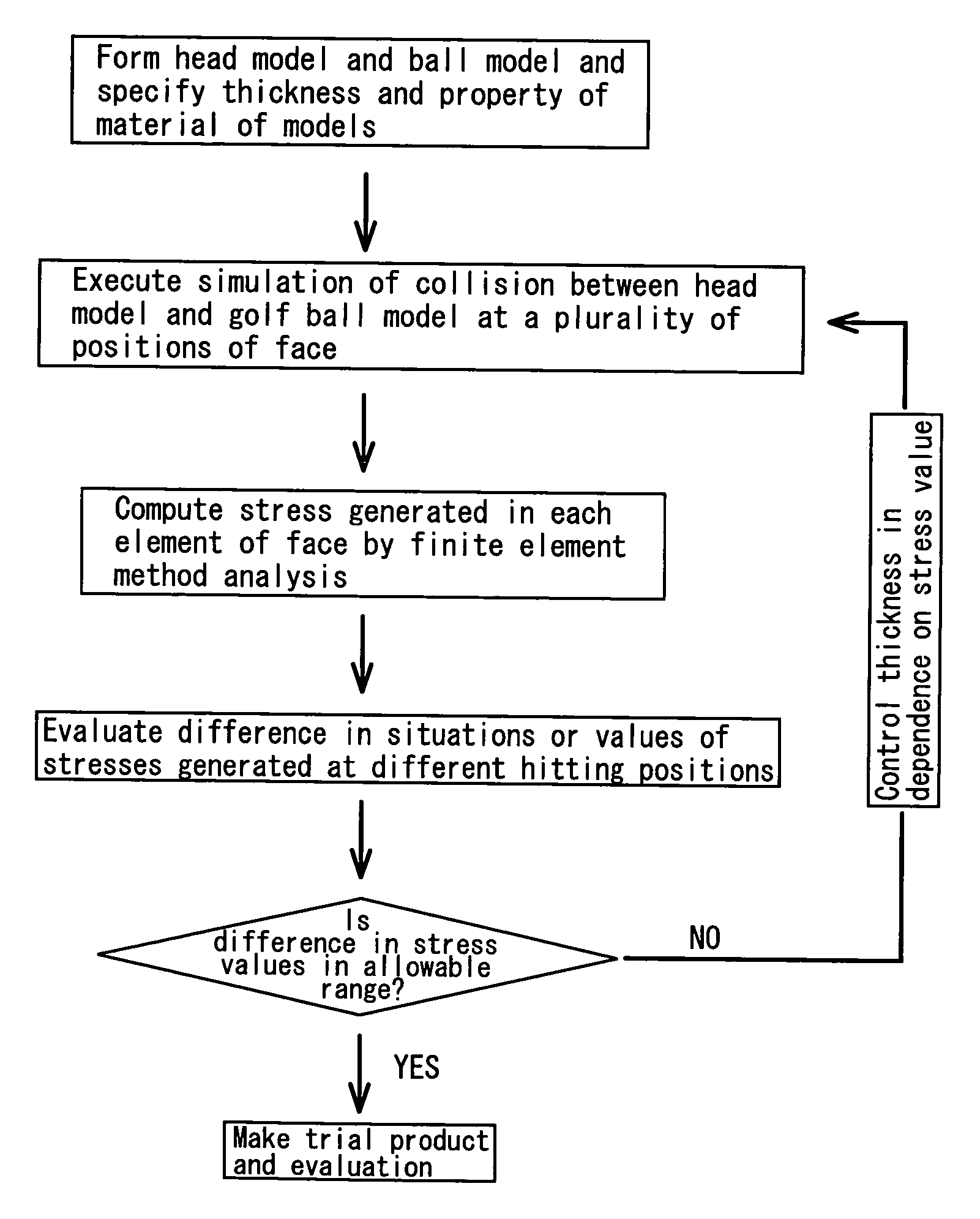
[0131] Golf club head models of the examples 1 through 8 shown in table 1 and golf club head models of the comparison examples 1 through 4 shown in table 2 were formed by using a computer. Simulation was executed by collision between ball models and the golf club head models. The coefficient of restitution of each golf club head model was determined to evaluate the performance of the golf club head models.

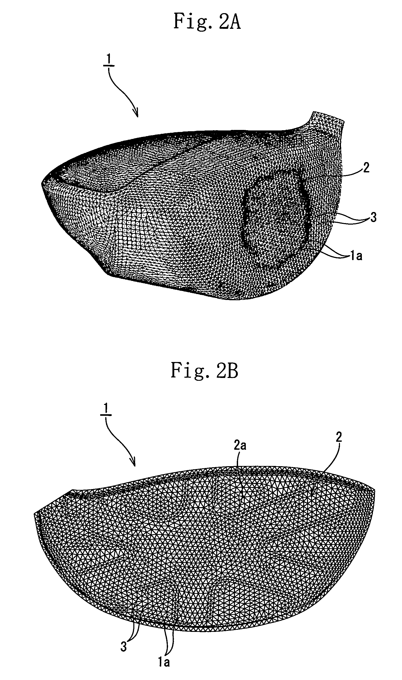
[0132] Excluding the reinforcing ribs of the face part, the golf club head models of all the examples and the comparison examples were prepared by using the same specification. More specifically, similarly to the embodiments shown in FIGS. 6 through 9, each of the hollow golf club head models made of a titanium alloy was formed by joining the face and body parts with each other to make them approximately cup-shaped. The head had a volume of 405 cc. The face part has an area of 4100 mm2. The thickness of the portion of the face part where the reinforcing ribs were not formed was se...


PUM


Abstract

A method for designing a golf club head by using a computer. A golf club head model in which the rear surface of a face part is provided with reinforcing ribs and a golf ball model to be analyzed by using a finite element method (FEM) are prepared. Conditions including the positions of the reinforcing ribs and the configurations thereof including the sectional areas and heights are adjusted to set the maximum value of the Mises stresses generated by the collision between the golf ball model and the golf club head model at any off-center positions of said front surface of said face part thereof to less than 1.3 times the maximum value of the Mises stress generated by the collision between the golf ball model and the golf club head model at the center of said front surface of said face part thereof.

Description

[0001] This nonprovisional application claims priority under 35 U.S.C. §119(a) on Patent Application No(s). 2005-202727 filed in Japan on Jul. 12, 2005, the entire contents of which are hereby incorporated by reference.BACKGROUND OF THE INVENTION [0002] 1. Field of the Invention [0003] The present invention relates to a method of designing a golf club head by utilizing a computer. The present invention also relates to a golf club head. More particularly, the present invention relates to a method of efficiently designing a golf club head having a sufficient strength and excellent restitution characteristics. To do so, a golf ball model and a golf club head model both composed of a plurality of finite elements are used. Further reinforcing ribs are formed on the rear surface of the face part of the golf club head model. By changing conditions of the reinforcing ribs, ball-hitting simulation is executed to make stresses generated at any hitting positions of the face part uniform. [0004...

Claims


Application Information

Patent Timeline
IPC IPC(8): A63B53/00A63B102/32G06F17/50
CPCA63B53/04A63B53/0466A63B2053/0416A63B2053/0408G06F17/5018A63B2053/0458A63B2053/0454A63B2053/045G06F30/23A63B60/00A63B53/0454A63B53/045A63B53/0458A63B53/0408A63B53/0416
Inventor TSUNODA, MASAYANISHIO, MASAYOSHI
Owner DUNLOP SPORTS CO LTD
Why Eureka
Try Eureka