Radio therapy apparatus and operating method of the same

a radiotherapy apparatus and radiotherapy technology, applied in the field of radiotherapy apparatus and radiotherapy apparatus, can solve the problems of inability to carry out stereotaxic radiotherapy on the body, inability to track the movement of the radiation field at the high speed, and inability to carry out position control at a high speed

Inactive Publication Date: 2007-01-18
MITSUBISHI HEAVY IND LTD
View PDF14 Cites 91 Cited by
  • Summary
  • Abstract
  • Description
  • Claims
  • Application Information

AI Technical Summary

Benefits of technology

[0020] Therefore, an object of the present invention is to provide a radio-therapy apparatus, in which a therapy plan can be easily planned after a radio-therapy is carried out on a specimen, and an operating method of the radio-therapy apparatus.

Problems solved by technology

However, since the radiation field of the radiation irradiating unit is fixed, the stereo-taxic radio-therapy cannot be carried out on the body that the radiation field such as the tumor is moved by the influence of the motions and situations of the organs below a neck, e.g., the respiration and beat, the peristalsis, a urine amount inside a bladder, and the like.
However, in this linear acceleration therapy apparatus, it is impossible to carry out a position control at a high speed.
Thus, it is impossible to track a radiation field moving at the high speed due to the beat of the heart and the like in real time.
However, since the therapeutic X-ray has a strong transmission and many scattered lines, the therapeutic X-ray is unsuitable for the real time monitor of the radiation field.
However, since the synchronous radiation is carried out by predicting the position of the diseased portion and irradiating the radiation beam towards the predicted position, the therapeutic radiation is not necessarily carried out the while tracking the diseased portion in the real time.
However, in this apparatus, although a fixing tool is used for fixing the head in case of the head therapy, the irradiation is not always irradiated while the images of the diseased portion are directly observed.
Also, the electronic linear accelerator is heavy in weight.
Also, the industrial robot arm does not insure the absolute precision to a specified space coordinate, and it only insures the repetition precision through teaching.
However, an irradiating method is isocentric and is similar to the radio surgery therapy apparatus in the point that the head needs to be fixed by the frame.
Also, this conventional example is different from the radio surgery therapy apparatus in that the large gantry is driven with the two shafts.
Also, although the respiration and beat are the cyclic operations, the motions of the respective organs associated with it do not always pass through the same route every time.
However, since the radiation record during the radio-therapy is not always recorded, the portion to which the radio-therapy is actually carried out is unclear.
Thus, it cannot be said to be sufficient as a record of the radio-therapy history, which brings about a problem that a new radio-therapy plan is difficult.
Thus, since there is no data indicating the radiation state under the radio-therapy, the portion to which the therapeutic radiation is irradiated and the radiation dose amount at that time are unobvious.
Therefore, there is a problem that it is difficult for the doctor to check the therapy state, to plan a next therapy action and to determine whether or not a present radio-therapy is proper.
However, whether or not the therapy content is proper cannot be determined, and the quality of the therapy is not evident.
However, this method has a problem that the coordinate data of the diseased portion of the patient is not known, and the direction of the radiation is unclear, and the check for the therapy plan is difficult.

Method used


Image

  • Radio therapy apparatus and operating method of the same
  • Radio therapy apparatus and operating method of the same
  • Radio therapy apparatus and operating method of the same

Examples


Embodiment Construction

[0058] Hereinafter, a radio-therapy apparatus of the present invention will be described in detail with reference to the attached drawings.

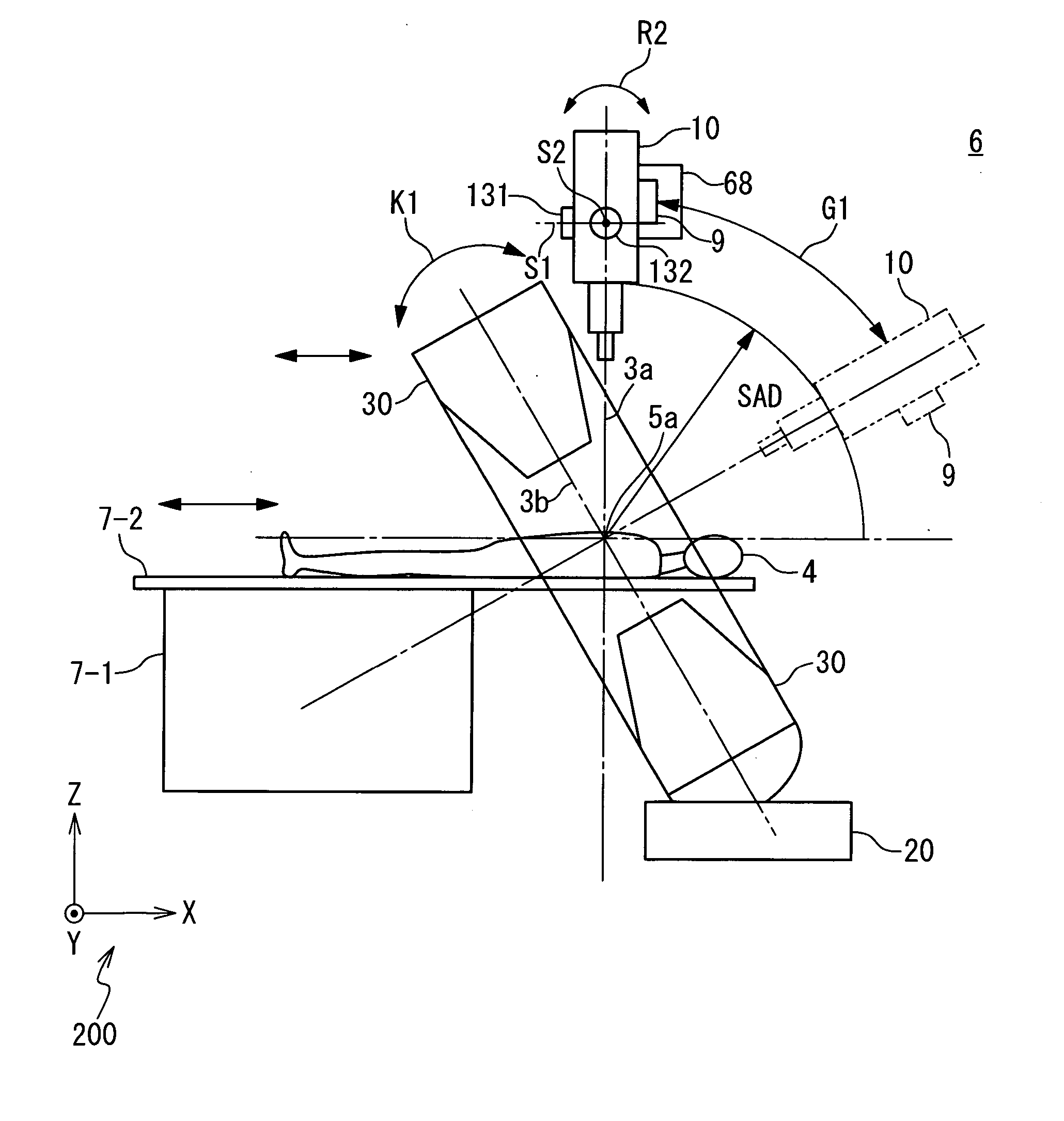
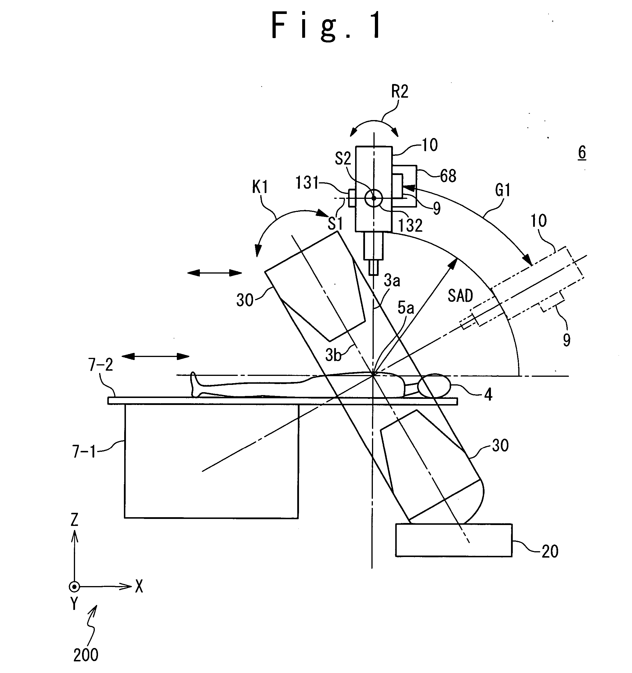
[0059]FIG. 1 is a side view of the radio-therapy apparatus according to an embodiment of the present invention, FIG. 2 is its front view, and FIG. 3 is a perspective view. It should be noted that a part of the radio-therapy apparatus is omitted in these drawings. A coordinate system 200 indicates a three-dimensional orthogonal coordinate system having an X-axis, a Y-axis and a Z-axis in FIGS. 1 to 3.

[0060] A radio-therapy apparatus 6 includes a therapeutic bed system 7, an X-ray head 10, a first swinging mechanism 131, a second swinging mechanism 132, an arc guide rail 9, a microwave generating unit 70, a tracking type waveguide system 11 and a real time imager 30.

[0061] The therapeutic bed system 7 is provided with a bed driving system 7-1, a therapeutic bed 7-2 and a patient fixing unit 7-3. The therapeutic bed 7-2 movably supports a patient...


PUM


Abstract

A radio-therapy apparatus includes a radiation head configured to irradiate a therapeutic radiation, and an image processing section configured to generate an image of a diseased portion of a specimen from a result of detection of the diseased portion while tracking the diseased portion to which the therapeutic radiation is irradiated from the radiation head. A control section controls the radiation head and the image processing section such that a period containing the generation of the image and the irradiation of the therapeutic radiation is repeated and the detection of the diseased portion in a next period is started prior to an end of a current period. A recording section records the image of the diseased portion generated by the image processing section in order.

Description

CROSS REFERENCE [0001] This application is related to the U.S. patent application Ser. No. 11 / 067013. The disclosure of the U.S. patent application Ser. No. 11 / 067013 is incorporated herein by reference.BACKGROUND OF THE INVENTION [0002] 1. Field of the Invention [0003] The present invention relates to a radio-therapy apparatus and a method of operating a radio-therapy apparatus, and more particularly relates to a technique for recording a therapy history at a time of radio-therapy. [0004] 2. Description of the Related Art [0005] Conventionally, a radio-therapy apparatus for treating a cancer and a tumor by using radiation is known. A radio surgery therapy apparatus, a linear accelerator therapy apparatus and the like are known as a three-dimensional radio-therapy apparatus for stereo-taxic multi-orbit radiation. The stereo-taxic multi-orbit radiation is a radio-therapy method of intensively irradiating a radiation beam to a small nidus from many directions to improve the radio-ther...

Claims


Application Information

Patent Timeline
Patent Type & Authority Applications(United States)
IPC IPC(8): A61B5/05A61N5/10
CPCA61N5/10A61N5/1038A61N2005/1061A61N5/1065A61N5/1082A61N5/1049
Inventor HARA, KENJIAKATSU, MAKOTOKAWATA, NORIYUKI
Owner MITSUBISHI HEAVY IND LTD
Why Eureka
Try Eureka