Dynamic fixation device and method of use

a technology of dynamic fixation and fixed device, which is applied in the field of securement devices, can solve the problems of instability, pain and neurologic compromise in some patients, local breakdown and excessive wear, etc., and achieve the effects of reducing pain or arthritis, avoiding instability or neurologic deficit, and reducing stress and motion

Inactive Publication Date: 2007-01-18
RITLAND STEPHEN
View PDF99 Cites 239 Cited by
  • Summary
  • Abstract
  • Description
  • Claims
  • Application Information

AI Technical Summary

Benefits of technology

[0020] A group of geometries exist, which if applied to a posterior device, will constrain the subluxation of the segment and maintain the rotation in or close to the normal zone or axis of rotation. The indication for use is to constrain the stresses and motion within a range which will allow the body's normal healing response to maintain adequate competence in the motion segment to avoid development of instability or neurologic deficit and minimize pain or arthritis. The important features allow for maintenance of physiologic motion without the abnormal subluxation or translation that are associated with a degenerating disk and contribute to further degeneration. Thus, it is a separate aspect of the invention to provide a construct that limits excessive subluxation or translation.
[0021] Although the mo...

Problems solved by technology

In some cases, however, the trauma or stress exceeds the ability of the body to heal, leading to local breakdown and excessive wear, and frequently also leads to local instability.
Accordingly, degenerative change with age superimposed on baseline anatomy in the lumbar spine leads to problems including instability, pain and neurologic compromise in some patients.
In some cases, the local anatomy may not provide the same protection to the motion segment, thereby aggravating this breakdown.
Although rehabilitation, conditioning, the limitation of stress, and time to recover are effective treatments for most patients, there is a significant failure rate with persistent pain, disability and potential neurologic deficit.
In some cases, the recurrent loads and motion on the disk and associated trauma to disk and motion segment exceed the natural rate of healing or repair of the body.
In this situation, there is breakdown in the motion segment associated with loss of the normal axis of rotation.
A challenge in designing such a system is constraining motion in a normal physiologic range.
Rigid fusion constructs do not allow relative movement between the vertebrae that are fused using a construct comprising a pedicle screw, connector mechanism, and rigid rod.
Furthermore, rigid implants are known to create significant amounts of stress on the components of the construct, including the pedicle screws and the rod, as well as the bone structure itself.
These stresses may even cause the rigid rod to break.
In addition, the stresses transferred to the pedicle screws may cause the screw...

Method used


Image

  • Dynamic fixation device and method of use
  • Dynamic fixation device and method of use
  • Dynamic fixation device and method of use

Examples


Embodiment Construction

[0066] While the present invention will be described more fully hereinafter with reference to the accompanying drawings in which particular embodiments and methods of implantation are shown, it is to be understood at the outset that persons skilled in the art may modify the invention herein described while achieving the functions and results of this invention. Accordingly, the descriptions which follow are to be understood as illustrative and exemplary of specific structures, aspects and features within the broad scope of the present invention and not as limiting of such broad scope.

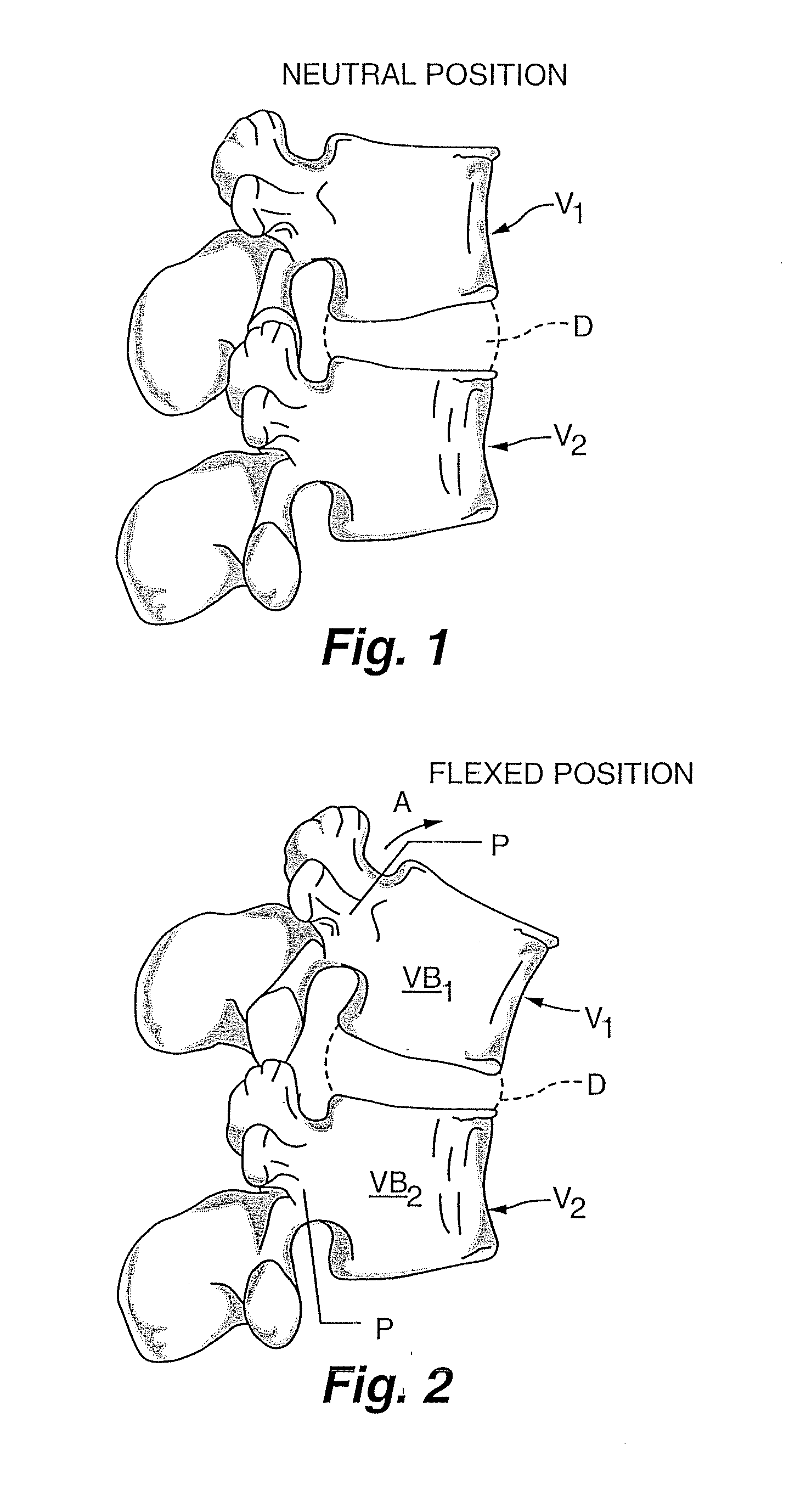
[0067] As noted above, at each intervertebral joint or disc D, flexion involves a combination of anterior sagittal rotation and a small amplitude anterior translation. The various embodiments of the present invention allow for controlled rotation while limiting translation within an acceptable, normal physiological range.

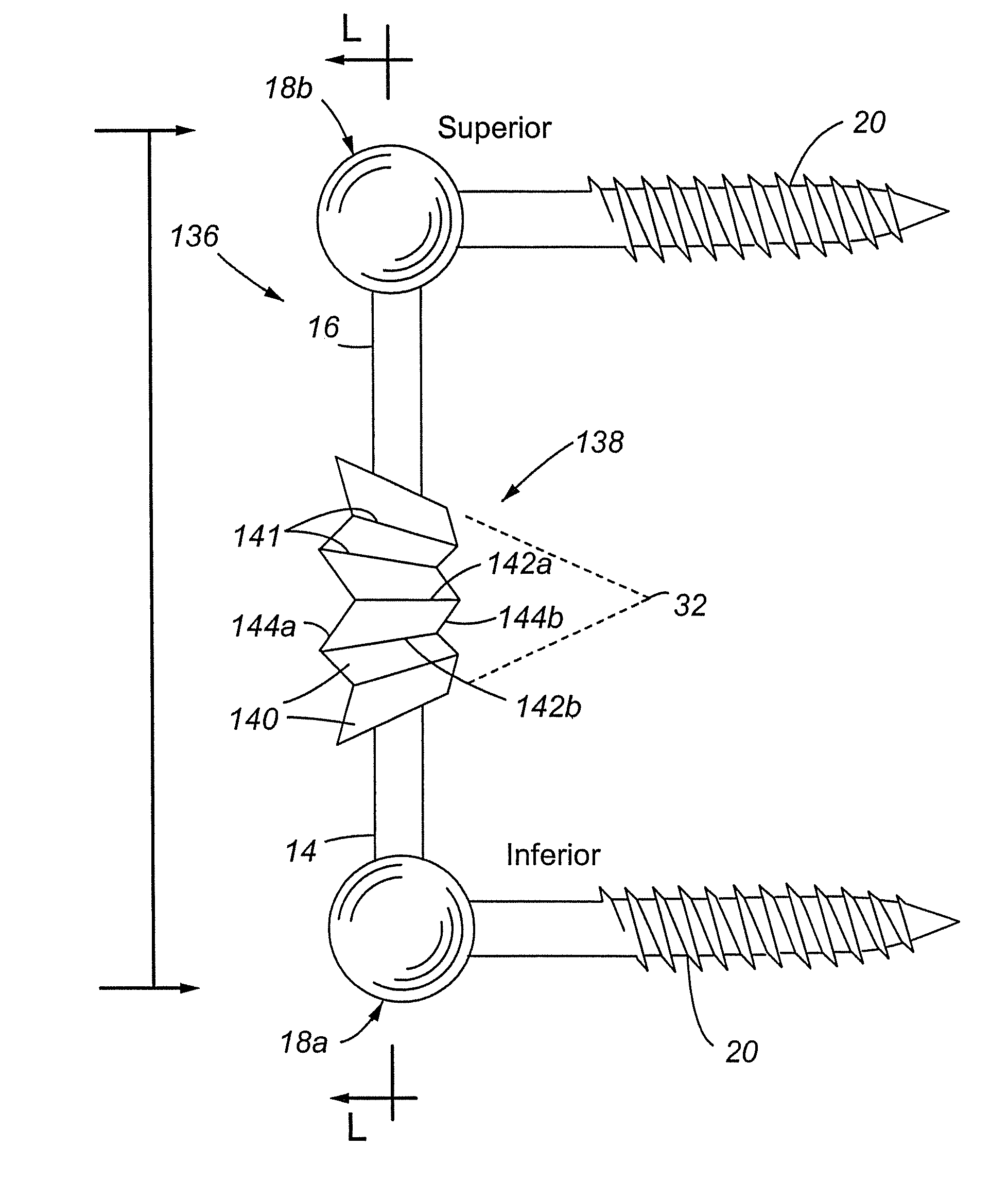
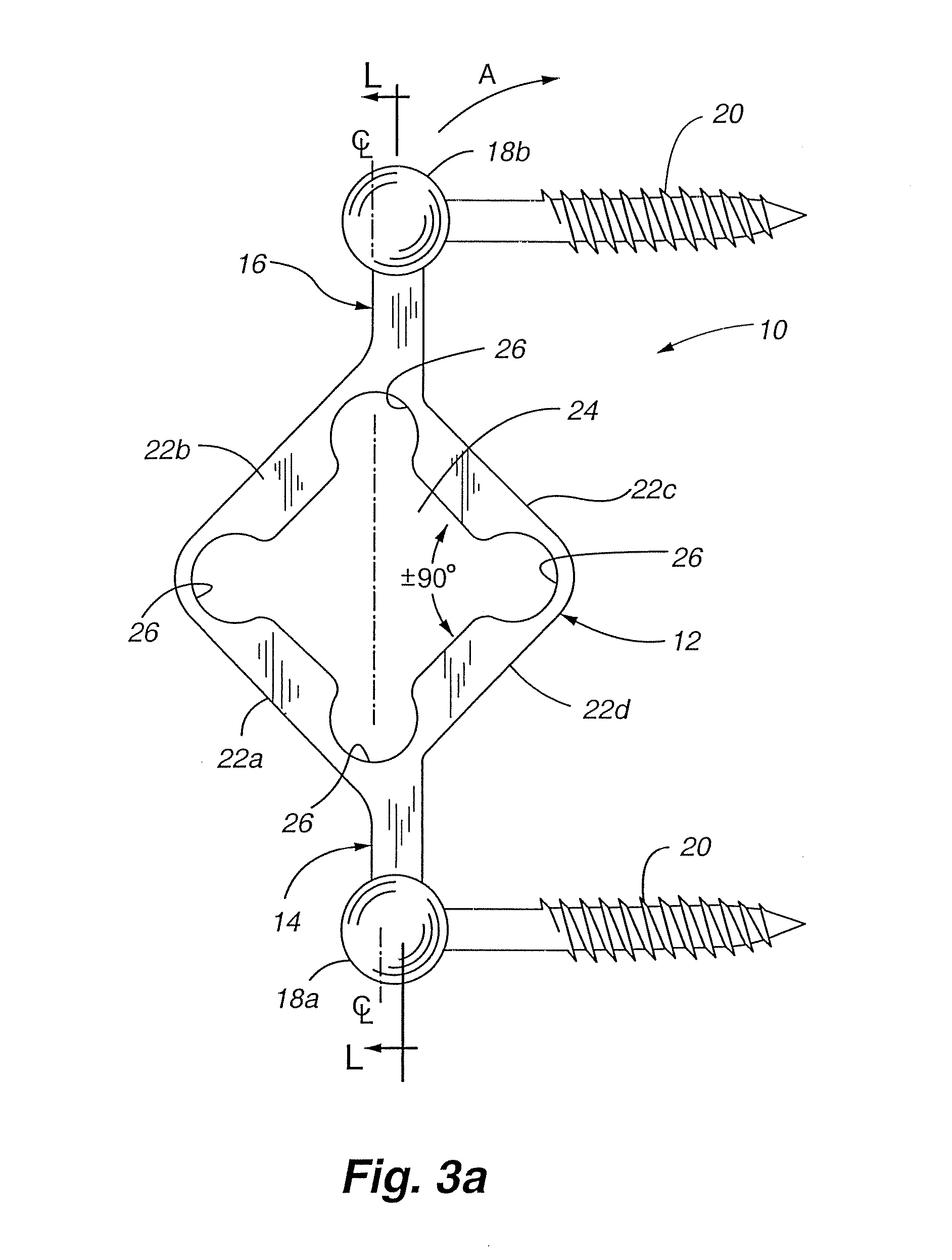
[0068] Referring now to FIG. 3a, a side elevation view of a first embodiment of a ...


PUM


Abstract

A dynamic fixation device is provided that allows the vertebrae to which it is attached to move in flexion within the normal physiological limits of motion, while also providing structural support that limits the amount of translation motion beyond normal physiological limits. The present invention includes a flexible portion and two ends that are adapted for connection to pedicle screws. In at least one embodiment of the present invention, the normal axis of rotation of the vertebrae is substantially duplicated by the dynamic fixation device. The flexible portion of the dynamic fixation device can include a flexible anterior-posterior segment, an anterior-posterior segment bounded by one or more zones with cuts in the rod portions, a flexible accordion-like segment, and/or a hinge portion.

Description

CROSS-REFERENCE TO RELATED APPLICATIONS [0001] The present application is a continuation-in-part application of U.S. patent application Ser. No. 10 / 435,330 filed May 8, 2003, which claimed the benefit of U.S. Provisional Patent Application No. 60 / 379,167 filed May 8, 2002, U.S. Provisional Patent Application No. 60 / 390,181 filed Jun. 19, 2002, and U.S. Provisional Patent Application No. 60 / 417,722 filed Oct. 9, 2002; in addition, the present application claims the benefit of U.S. Provisional Patent Application No. 60 / 693,126 filed Jun. 22, 2005. All of the above-referenced patent application are incorporated herein by reference in their entireties. Cross reference and incorporation thereof is also made to pending U.S. patent application Ser. No. 11 / 223,530 filed Sep. 9, 2005.FIELD OF THE INVENTION [0002] This invention relates generally to securement devices and, more particularly, to a device capable of flexibly securing vertebrae together. BACKGROUND OF THE INVENTION [0003] The lu...

Claims


Application Information

Patent Timeline
IPC IPC(8): A61F2/30A61BA61B1/00A61B17/00A61B17/56A61B17/70
CPCA61B17/7004A61B17/7011A61B2017/00004A61B17/7026A61B17/7023A61B17/7002A61B2017/00526A61B2017/00867
Inventor RITLAND, STEPHEN
Owner RITLAND STEPHEN
Why Eureka
Try Eureka