Communication system, and master apparatus and slave apparatus used in the same, and communication method

a communication system and master apparatus technology, applied in the field of serial data communication, can solve the problems of increasing the number of slaves, increasing the size of the memory, increasing the functional complexity, etc., and achieve the effect of high speed

Inactive Publication Date: 2007-01-18
COLLABO INNOVATIONS INC
View PDF4 Cites 7 Cited by
  • Summary
  • Abstract
  • Description
  • Claims
  • Application Information

AI Technical Summary

Benefits of technology

[0048] As described above, according to the present invention, a communication system and a communication method are provided that allow a master to read desired data from a slave at a high speed. Further, accor...

Problems solved by technology

This problem need be resolved in the situation that the amount of data transmitted from the slave 4 increases with increasing scale ...

Method used


Image

  • Communication system, and master apparatus and slave apparatus used in the same, and communication method
  • Communication system, and master apparatus and slave apparatus used in the same, and communication method
  • Communication system, and master apparatus and slave apparatus used in the same, and communication method

Examples


first embodiment

[0057] A communication system according to a first embodiment of the present invention is described below with reference to the drawings. Here, the same or like components as those of the background art are designated by the same or like reference numerals.

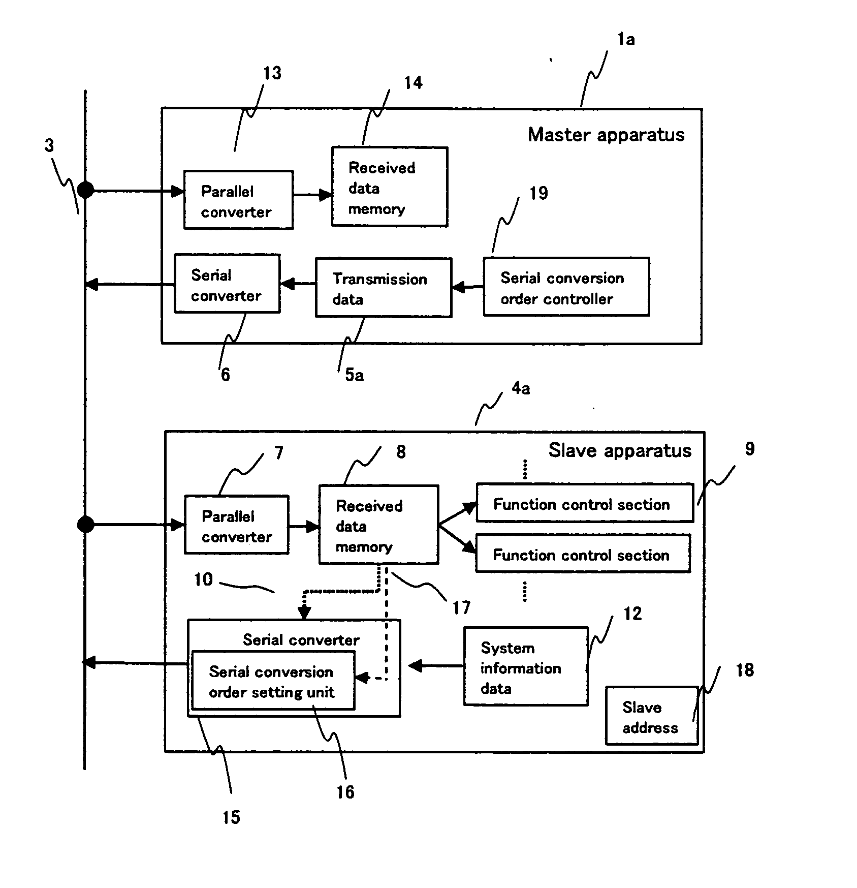
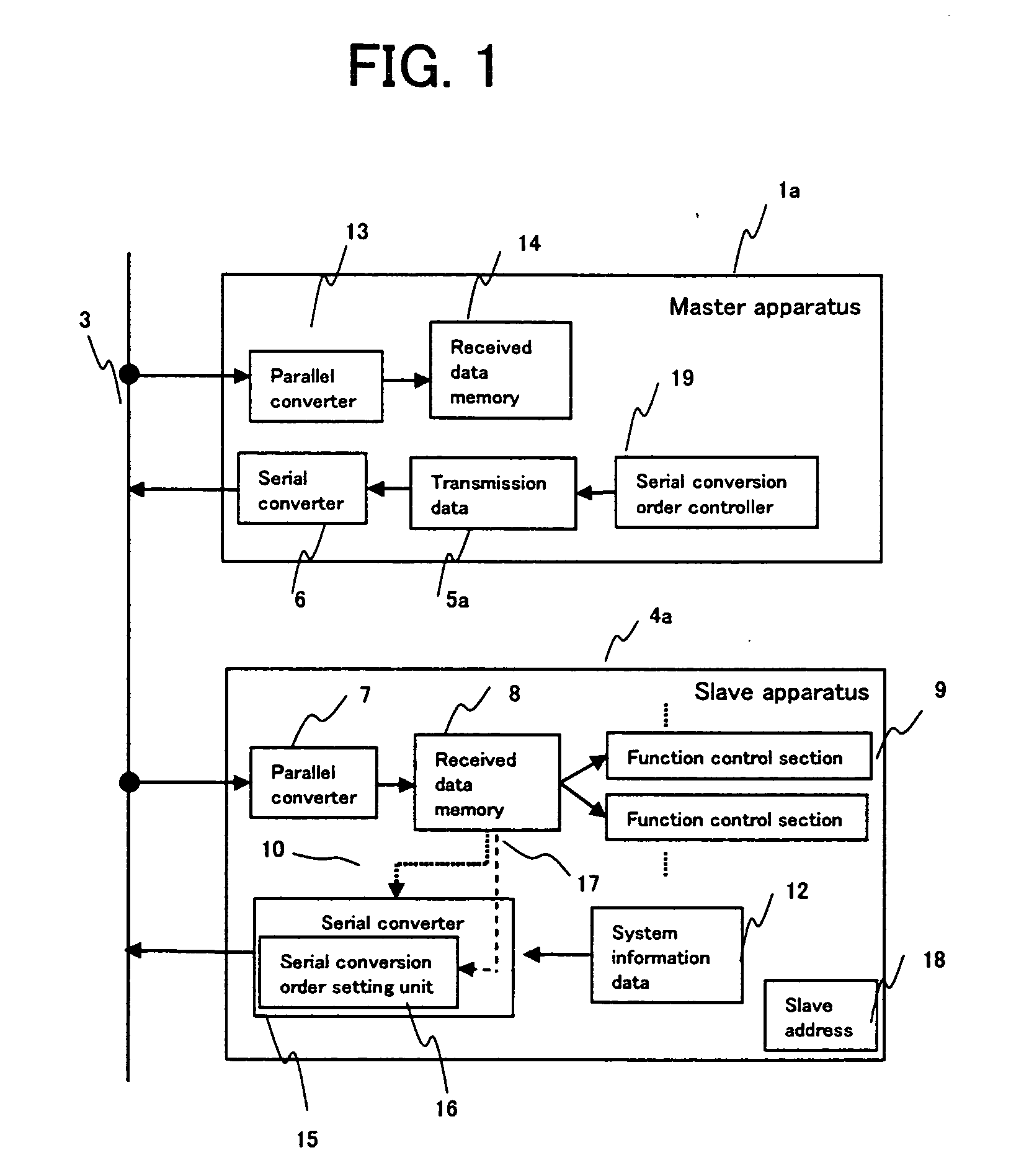
[0058]FIG. 1 is a diagram showing a configuration of a communication system according to a first embodiment of the present invention. As shown in FIG. 1, the communication system according to the present embodiment comprises: a master 1a for controlling data transfer; a slave 4a which is addressed by the master 1a and data transfer of which is controlled by the master 1a; and a serial data line 3 for performing data transfer between the master 1a and the slave 4a. In FIG. 1, a single slave 4a is solely shown. However, actually, a plurality of slaves 4 are connected to the serial data line 3 as shown in FIG. 6. Further, between the master 1a and the slave 4a, a serial clock line 2 of FIG. 6 is also arranged in addition to the seri...

second embodiment

[0070] A communication system according to a second embodiment of the present invention is described below with reference to the drawings. Here, the same or like components as those of the background art are designated by the same or like reference numerals.

[0071]FIG. 3 is a diagram showing a configuration of a communication system according to a second embodiment of the present invention. The communication system according to the present embodiment comprises: a master 1b for controlling data transfer; a slave 4b which is addressed by the master 1b and data transfer of which is controlled by the master 1b; and a serial data line 3 for performing data transfer between the master 1b and the slave 4b. In FIG. 3, a single slave 4b is solely shown. However, actually, a plurality of slaves 4b are connected to the serial data line 3. Further, between the master 1b and each slave 4b, a serial clock line 2 of FIG. 6 is also arranged in addition to the serial data line 3.

[0072] Next, the op...


PUM


Abstract

This communication system performs serial data communication between a master apparatus and a plurality of the slave apparatus via a data transmission line. The master apparatus generates, by using a controller, a serial conversion order control signal for controlling serial conversion order for the data in the slave apparatus, and then transmits the signal to the slave apparatus. The slave apparatus sets up serial conversion order for system information data in accordance with the serial conversion order control signal, then performs serial conversion in accordance with the set-up order, and then transmits the serial conversion data to the master apparatus. The master apparatus can read the system information data in the slave apparatus in the order specified by the serial conversion order control signal.

Description

BACKGROUND OF THE INVENTION [0001] 1. Field of Invention [0002] The present invention relates to a data communication method and, in particular, to serial data communication for a television device, a video device, a DVD recorder device, an audio device, or the like. [0003] 2. Prior Art [0004] In the prior art, methods of controlling data transfer are known in which a controlling semiconductor apparatus and a plurality of to-be-controlled semiconductor apparatuses are interconnected using two or three transmission lines. Among such techniques, the Philips INTER-IC (I2C) bus is described below. [0005] An I2C bus is shown in FIG. 6. As shown in FIG. 6, in the I2C bus, a controlling semiconductor apparatus (referred to as a “master”, hereinafter) 1 and a plurality of to-be-controlled semiconductor apparatuses (each referred to as a “slave”, hereinafter) 4 are interconnected using two transmission lines 2 and 3. The master 1 controls each slave 4 via the transmission lines 2 and 3. [000...

Claims


Application Information

Patent Timeline
IPC IPC(8): G05B19/18G05B11/01
CPCG05B19/0421G05B2219/25178G05B2219/2231
Inventor KUSUMI, TORUUNO, YASUHIRO
Owner COLLABO INNOVATIONS INC
Why Eureka
Try Eureka