Micromachined thermal mass flow sensors and insertion type flow meters and manufacture methods

Inactive Publication Date: 2007-01-25
M TECH INSTR HLDG
View PDF8 Cites 29 Cited by
  • Summary
  • Abstract
  • Description
  • Claims
  • Application Information

AI Technical Summary

Benefits of technology

[0014] According it is an object of the present invention to provide a MEMS mass flow sensor and MEMS flow sensor array with significantly increase

Problems solved by technology

Conventional technologies of mass flow sensors are still limited by the difficulties of limited ranges of flow rate measurement, low accuracy and the requirement to maintain a high level of heating power.
The stream of flow when passing over the mass flow sensor, carries away the heat from the heater thus causes temperature variations.
However, as further discussed below, the limited ranges of flow rate measurements and the technical difficulties in improving the measurement accuracy are still the hindrances to broadly apply a MEMS flow sensor in different applications.
This means that the pulse tends to be too broad to be useful for slow flows and thus become inaccurate.
In general, A-type mass flow sensors are less sensitive in small flows and hence cannot measure small flows accurately.
H

Method used


Image

  • Micromachined thermal mass flow sensors and insertion type flow meters and manufacture methods
  • Micromachined thermal mass flow sensors and insertion type flow meters and manufacture methods
  • Micromachined thermal mass flow sensors and insertion type flow meters and manufacture methods

Examples


Embodiment Construction

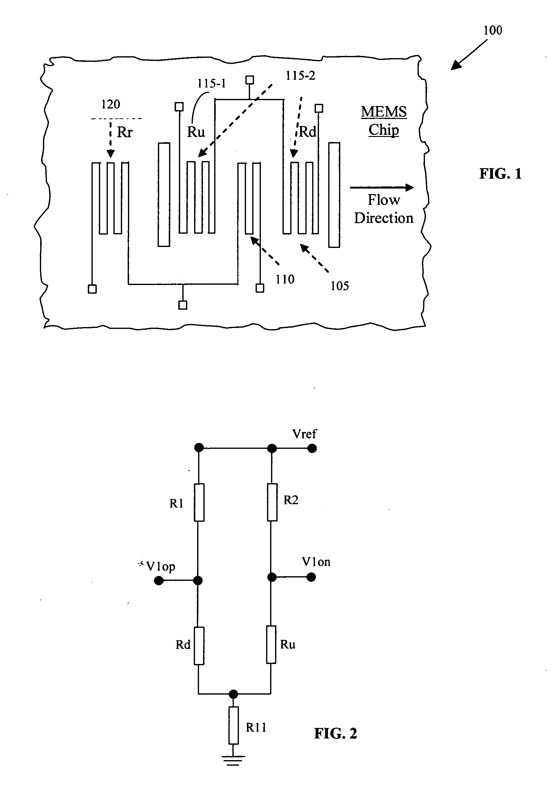
[0043]FIG. 1 shows a top view of a flow rate sensor 100 as a preferred embodiment of the present sensor. The flow rate sensor 100 is supported on a membrane 105 and is manufactured by applying the MEMS manufacturing processes as illustrated below. The flow rate sensor includes a heater 110 and temperature sensing resistors 115-1 and 115-2 disposed on the upstream and downstream respectively of the heater 110. The heater 110 is a thin-film heating element and the temperature sensing resistors 115-1 and 115-2 is a pair of thin-film sensing resistors on a thin thermally isolated membrane 105 disposed over a micro-machined silicon substrate. The upstream and downstream sensing resistors 115-1 and 115-2 respectively may be symmetrical, i.e., resistors of equal resistance, or non-symmetrical resistors, i.e., resistors of different resistances. The upstream and downstream sensing resistors may be arranged to locate at either a symmetrical or non-symmetrical locations. The flow rate sensor ...


PUM


Abstract

An integrated mass flow sensor is manufactured by a process of carrying out a micro-machining process on an N or P-type silicon substrate with orientation <100>. This mass flow sensor comprises a central thin-film heater and a pair of thin-film heat sensing elements, and a thermally isolated membrane for supporting the heater and the sensors out of contact with the substrate base. The mass flow sensor is arranged for integration on a same silicon substrate to form a one-dimensional or two-dimensional array in order to expand the dynamic measurement range. For each sensor, the thermally isolated membrane is formed by a process that includes a step of first depositing dielectric thin-film layers over the substrate and then performing a backside etching process on a bulk silicon with TMAH or KOH or carrying out a dry plasma etch until the bottom dielectric thin-film layer is exposed. Before backside etching the bulk silicon, rectangular openings are formed on the dielectric thin-film layers by applying a plasma etching to separate the area of heater and sensing elements from the rest of the membrane. This mass flow sensor is operated with two sets of circuits, a first circuit for measuring a flow rate in a first range of flow rates and a second circuit for measuring a flow rate in a second range of flow rates, to significantly increase range of flow rate measurements, while maintains a high degree of measurement accuracy.

Description


Claims


Application Information

Patent Timeline
Owner M TECH INSTR HLDG
Why Eureka
Try Eureka