
Vehicle power steering system

a technology for power steering and vehicles, applied in the field of vehicles, to achieve the effect of saving fuel consumption

Inactive Publication Date: 2007-01-25
YH AMERICA
View PDF20 Cites 0 Cited by
  • Summary
  • Abstract
  • Description
  • Claims
  • Application Information

AI Technical Summary

Benefits of technology

[0007] Several benefits and advantages are derived from one or more of the expressions of the embodiments of the invention. In one example, having at least one Hall sensor to sense steering wheel torque enables the at-least-one hydraulic-power-steering system valve to be electrically actuated and enables the power steering system to operate on demand which saves on fuel consumption, as can be appreciated by those skilled in the art. In the same or a different example, having valve control based on the output of a Hall sensor which depends on steering wheel torque and which is adjusted for measured fluid pressure, allows feedback control that converges on a desired pressure avoiding high frequency cycling events felt in the steering wheel of unsuccessful electric-controlled power steering systems which include a driver-to-vehicle feedback loop, as can be appreciated by the artisan.

Problems solved by technology

A driver turning the vehicle steering wheel results in twisting of the steering torsion bar which physically opens and closes hydraulic flow-control valves which results in high pressure fluid flowing to one side or the other side of a hydraulic piston which moves the wheel tie rods to turn the vehicle wheels.

Method used


Image

  • Vehicle power steering system
  • Vehicle power steering system
  • Vehicle power steering system

Examples


first embodiment

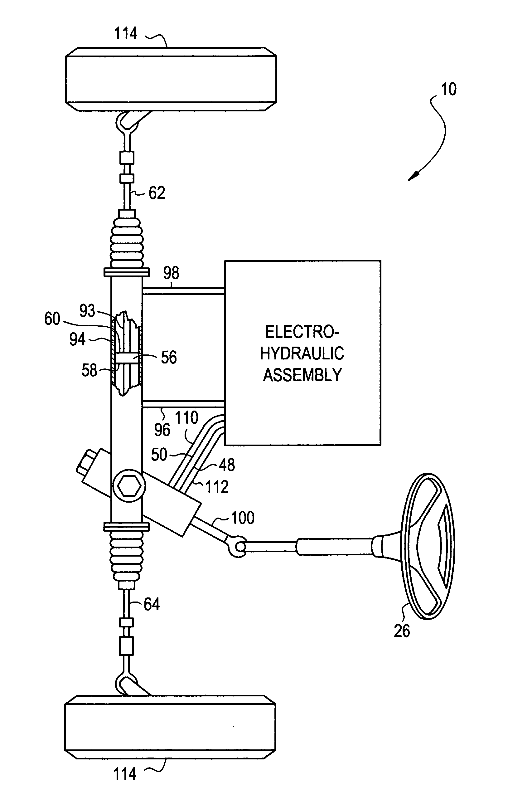
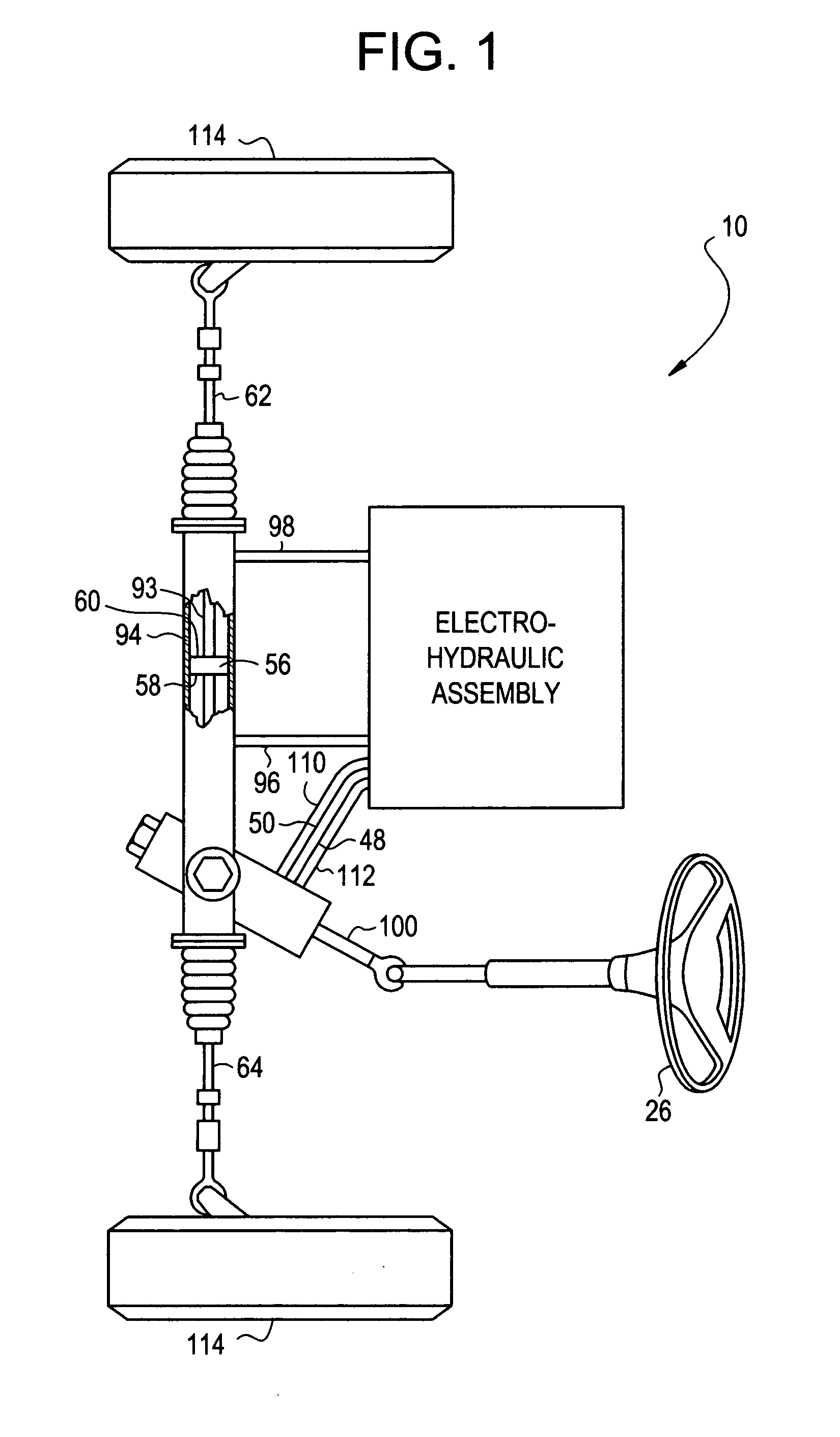
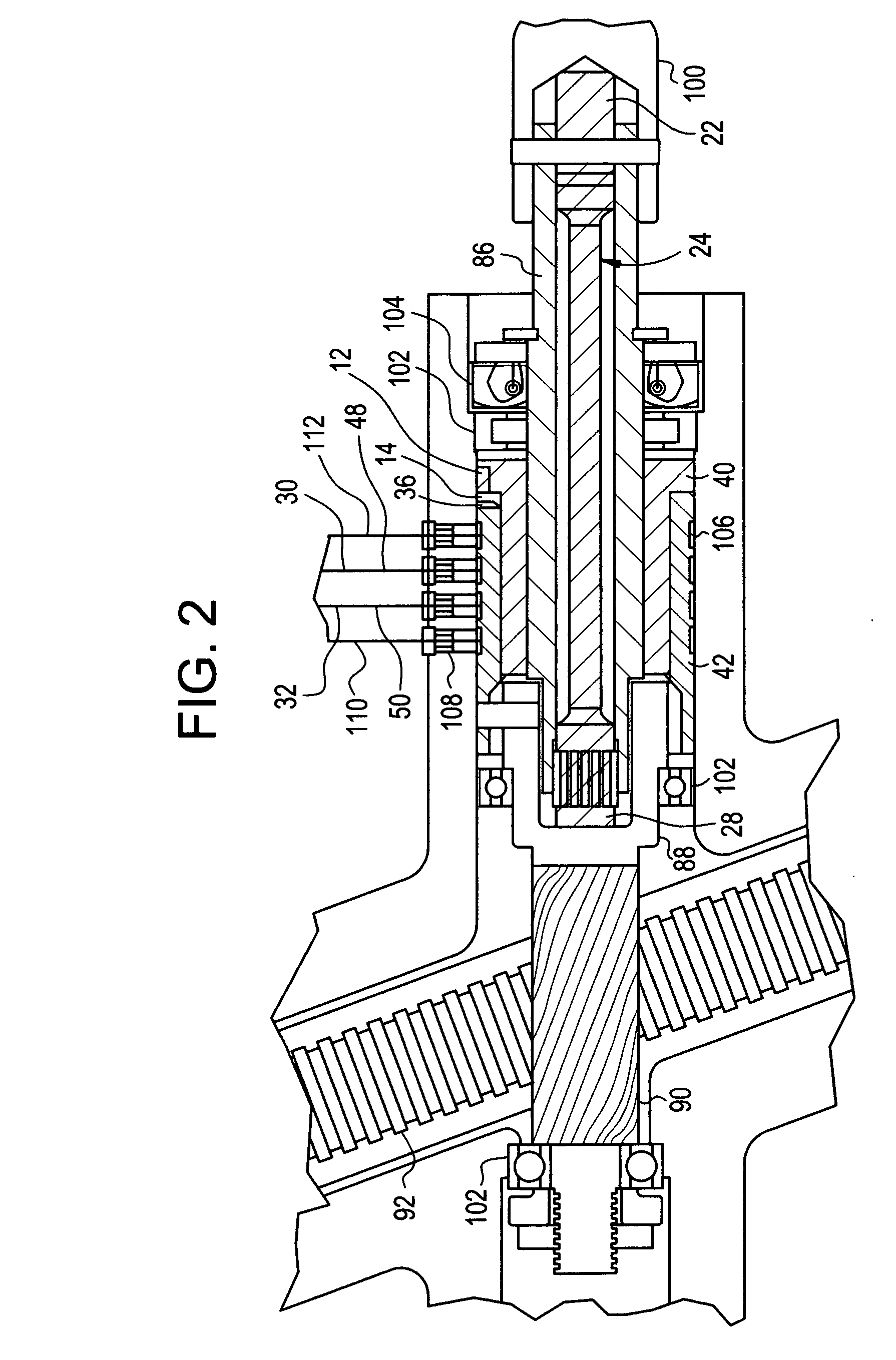
[0023] Referring now to the drawings, FIGS. 1-5 illustrate the present invention. A first expression of the embodiment of FIGS. 1-5 is for a vehicle power steering system 10 including a sweep magnet 12, at least one Hall sensor 14 and 16, and at least one hydraulic-power-steering-system valve 18 and 20. The sweep magnet 12 is fixedly connected to a first end 22 of a twistable steering torsion bar 24 wherein the first end 22 is fixedly connected to a vehicle steering wheel 26. The at least one Hall sensor 14 and 16 is fixedly connected to a second end 28 of the steering torsion bar 24. The at-least-one Hall sensor 14 and 16 has an output 30 and 32 and is disposed proximate the sweep magnet 12 such that the output 30 and 32 is a function of steering wheel torque when the vehicle steering wheel 26 is turned by a driver. The at least one hydraulic-power-steering-system valve 18 and 20 is operatively connected to the output 30 and 32.

[0024] The term “connected” includes directly connecte...

second embodiment

[0032] Referring again to the drawings, FIGS. 6-10 illustrate the present invention. An expression of the embodiment of FIGS. 6-10 is for a vehicle power steering system 110 including: a first cylinder 140; a second cylinder 142; a hydraulic-power-steering-system, electrically-actuated pressure-control valve 178; and a controller 134. The first cylinder 140 has a sweep magnet 112 and is fixedly connected to a first end 122 of a twistable steering torsion bar 124 wherein the first end 122 is fixedly connected to a vehicle steering wheel 126. The second cylinder 142 has circumferentially spaced apart first and second Hall sensors 114 and 116 and is fixedly connected to a second end 128 of the steering torsion bar 124. The second cylinder 142 is substantially coaxially aligned with the first cylinder 140. The first and second Hall sensors 114 and 116 have corresponding first and second voltage outputs 148 and 150 and are disposed proximate the sweep magnet 112 such that the first and s...


PUM


Abstract

A vehicle power steering system includes a sweep magnet, at least one Hall sensor, and at least one hydraulic-power-steering-system valve. The sweep magnet is fixedly connected to a first end of a twistable steering torsion bar wherein the first end is fixedly connected to a vehicle steering wheel. The at-least-one Hall sensor is fixedly connected to a second end of the steering torsion bar. The at-least-one Hall sensor has an output and is positioned proximate the sweep magnet such that the output is a function of steering wheel torque when the vehicle steering wheel is turned by a driver. The at-least-one hydraulic-power-steering-system valve is operatively connected to the output.

Description

TECHNICAL FIELD [0001] The present invention relates generally to vehicles, and more particularly to a vehicle power steering system. BACKGROUND OF THE INVENTION [0002] Conventional vehicle power steering systems, such as ones used in automobiles and light trucks, use a continuously operating hydraulic pump and a twistable steering torsion bar connected at one end to a vehicle steering wheel and connected at the other end to the pinion gear of the steering system. A driver turning the vehicle steering wheel results in twisting of the steering torsion bar which physically opens and closes hydraulic flow-control valves which results in high pressure fluid flowing to one side or the other side of a hydraulic piston which moves the wheel tie rods to turn the vehicle wheels. Unsuccessful attempts at designing an electric-controlled hydraulic system, which involved the steering torsion bar in the valve control loop to produce a pressure level, are known. [0003] Still, scientists and engin...

Claims


Application Information

Patent Timeline
Patent Type & Authority Applications(United States)
IPC IPC(8): B62D5/04
CPCB62D5/09
Inventor EDSON, JOEY D.ENGEL, KLAUS G.FOSTER, RANDY C.JANKOVIC, ALEKSANDARMECKSTROTH, RICHARD J.
Owner YH AMERICA
Learn More