Device and method for lighting high-voltage discharge lamp

Active Publication Date: 2007-01-25
PANASONIC CORP
View PDF5 Cites 16 Cited by
  • Summary
  • Abstract
  • Description
  • Claims
  • Application Information

AI Technical Summary

Benefits of technology

[0042] With this method, the lamp electrode can be warmed rapidly, thereby m

Problems solved by technology

However, the amount of a substance such as mercury, which is enclosed in the lamp tube, is increased for the purpose of higher efficiency of the lamp, and the impedance increases due to explosive gasification of the enclosed substance, so that the lamp is unstable immediately after the lamp is turned ON.
In this situation, when the lamp is repeatedly turned ON and OFF, serious problems arise, such as a degradation in the lamp electrode, circuit destruction caused by an increase in noise due to repeated turning ON, and the like.
This type has the following drawback: due to the low frequency, there is a large difference in temperature between one lamp electrode being warmed and the other lamp not being warmed, so that current is likely to be interrupted when the polarity of current is switched.
However, due to the low-frequency start, there is a large difference in temperature between the two lamp electrodes, so that current is likely to be interrupted when the polarity of the current is switched.
As described above, the breakdown current Id through the lamp has a c

Method used


Image

  • Device and method for lighting high-voltage discharge lamp
  • Device and method for lighting high-voltage discharge lamp
  • Device and method for lighting high-voltage discharge lamp

Examples


Example

Embodiment 1

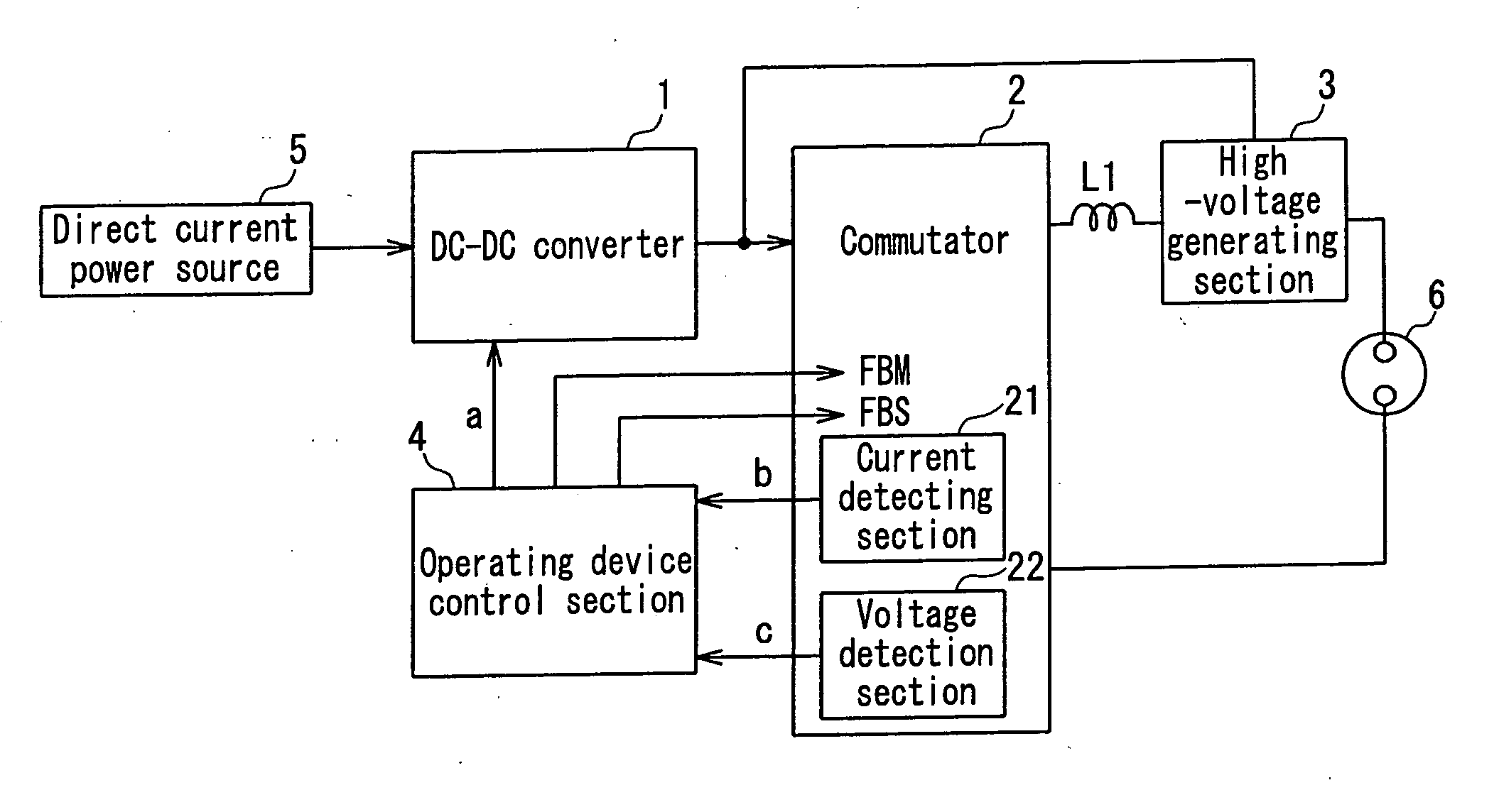
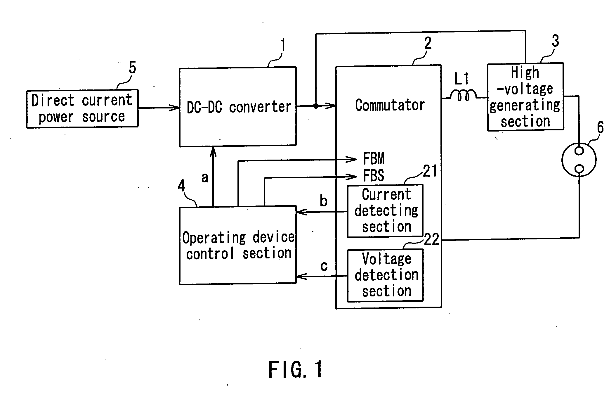
[0056]FIG. 1 is a circuit block diagram illustrating an exemplary structure of a ballast for a discharge lamp according to Embodiment 1 of the present invention. In FIG. 1, the ballast for a discharge lamp of Embodiment 1 of the present invention is composed of a direct current power source 5, a DC-DC converter 1 for DC-DC converting a current from the direct current power source 5 to generate a current that is to flow through a lamp 6, a commutator 2 for converting an output current (direct current) from the DC-DC converter 1 into an alternating current, a high-voltage generating section 3 for generating a high-voltage pulse that causes the lamp 6 to be broken down at the start of lamp operation, an operating device control section 4 for controlling an output current and an output voltage of the DC-DC converter 1 and a commutation frequency of the commutator 2, a choke coil L1 for reducing a time required to reverse the polarity of a lamp current, and the lamp 6, which...

Example

Embodiment 2

[0086] Embodiment 2 of the present invention will be described with reference to FIGS. 9, 3, and 4. FIG. 9 illustrates a circuit block diagram of Embodiment 2 of the present invention, which is the same as that of Embodiment 1, except that a lamp cooling device 7 is provided in the circuit block of FIG. 1. A circuit block diagram of an operating device control section 4 of Embodiment 2 of the present invention is substantially the same as that of Embodiment 1 of FIG. 3, except that an output d of a comparator is used as an input of the lamp cooling device 7 of FIG. 9.

[0087] Next, an operation of the ballast for a discharge lamp of Embodiment 2 of the present invention will be described. Note that the operation of the ballast for a discharge lamp of Embodiment 2 is the same as that of Embodiment 1, except for the operation involved with the lamp cooling device 7.

[0088] During the period T1 immediately after the start of lamp operation of FIG. 4, the lamp voltage value ...


PUM


Abstract

An operating device control section (4) controls an output current of a DC-DC converter (1), and also controls a commutation frequency of a commutator (2) that converts a direct current output from the DC-DC converter into an alternating current. The operating device control section operates a discharge lamp, at the start of lamp operation, with a predetermined voltage value lower than a rated voltage and a first target current value higher than a rated current, then, at an end of a predetermined high frequency start period (T1) elapsed from the start of lamp operation, controls the commutator to switch from a commutation frequency higher than that during a steady lamp operation to a commutation frequency during the steady lamp operation, and then, after a voltage applied to the discharge lamp increases and reaches a voltage not lower than a predetermined threshold voltage (Vth) which is not higher than the rated voltage, controls the DC-DC converter to switch from the first target current value to a second target current value which is not higher than the rated current to operate the discharge lamp. A temperature of a lamp electrode can be increased quickly and sufficiently to reduce a time required to increase the lamp illuminance, thereby reducing a time required to cause video to be viewable.

Description

TECHNICAL FIELD [0001] The present invention relates to a ballast for a discharge lamp, such as a high-pressure mercury lamp or the like and a method of operating the same, and is applicable to a projection-type projector system. BACKGROUND ART [0002] In recent years, the luminance of a projection-type projector has been improved dramatically by adopting a high-efficiency high-pressure discharge lamp (hereinafter simply referred to as a lamp). However, the amount of a substance such as mercury, which is enclosed in the lamp tube, is increased for the purpose of higher efficiency of the lamp, and the impedance increases due to explosive gasification of the enclosed substance, so that the lamp is unstable immediately after the lamp is turned ON. In this situation, when the lamp is repeatedly turned ON and OFF, serious problems arise, such as a degradation in the lamp electrode, circuit destruction caused by an increase in noise due to repeated turning ON, and the like. [0003] As a bal...

Claims


Application Information

Patent Timeline
IPC IPC(8): H05B41/36H05B41/288H05B41/38
CPCH05B41/2882H05B41/2883H05B41/2885Y02B20/204H05B41/386H05B41/388Y02B20/202H05B41/382Y02B20/00Y10S315/02Y10S315/05Y10S315/07
Inventor NOGUCHI, TOSHIYUKIKAKIMOTO, YASUHIRO
Owner PANASONIC CORP
Why Eureka
Try Eureka