Wireless sensor system, and bearing apparatus with wireless sensor

Inactive Publication Date: 2007-01-25
NTN CORP
View PDF30 Cites 41 Cited by
  • Summary
  • Abstract
  • Description
  • Claims
  • Application Information

AI Technical Summary

Benefits of technology

[0013] Considering that the monitored result information of the voltage of the electric power to be supplied can be transmitted, the receiving side of the sensor signal can recognize the monitored result information and, therefore, a countermeasure appropriate to the result of the monitoring can be taken. In particular, where the wireless supply of the electric power takes place from the feed power transmitting section, the provision of the monitor dependent control section (14) is effective to allow the electric power to be transmitted for the wireless electric power supply to be controlled in dependence on the monitored result information on the voltage of the electric power to be supplied. Accordingly, there is no need to transmit the large electric power at all times and the electric power consumption of the wireless sensor system can therefore be reduced.
[0014] The feed power transmitting section (12) referred to above may be provided in a sensor signal receiving unit (5) including the sensor signal receiving section (13). Where the monitor dependent control section (14) is employed, this monitor dependent control section (14) is also provided in the sensor signal receiving unit (5). Although the sensor signal receiving section (13) and the feed power transmitting means (12) may be arranged in spaced relation to each other, the provision of the both in the sensor signal receiving unit (5) is effective to simplify the structure of the wireless sensor system.
[0015] The electric power supply monitoring section (7) may be of a type capable of monitoring the voltage after the electric

Problems solved by technology

The wireless supply of the electric power tends to be adversely affected by obstacles present between the transmitter and the receiver and/or by a relative movement of the receiver to the transmitter, and vice versa, to such an extent as to result in failure to supply the sufficient amount of electric power and, therefore, care must be taken in selecting where to install.
For this reason, there is a problem in that continued supply of the large amount of electric power as a precaution against the failure of the electric power supply may result in increase

Method used


Image

  • Wireless sensor system, and bearing apparatus with wireless sensor
  • Wireless sensor system, and bearing apparatus with wireless sensor
  • Wireless sensor system, and bearing apparatus with wireless sensor

Examples


Example

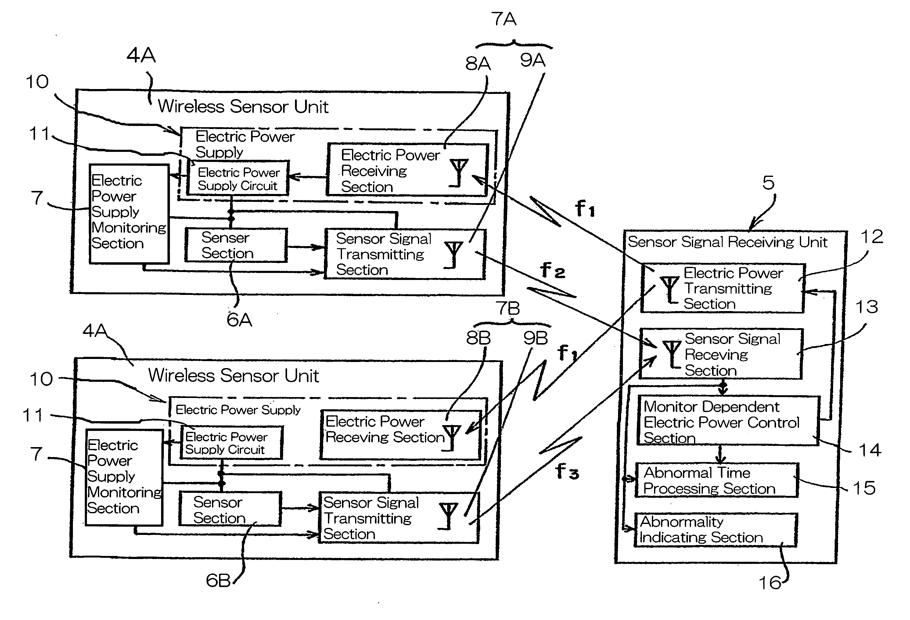
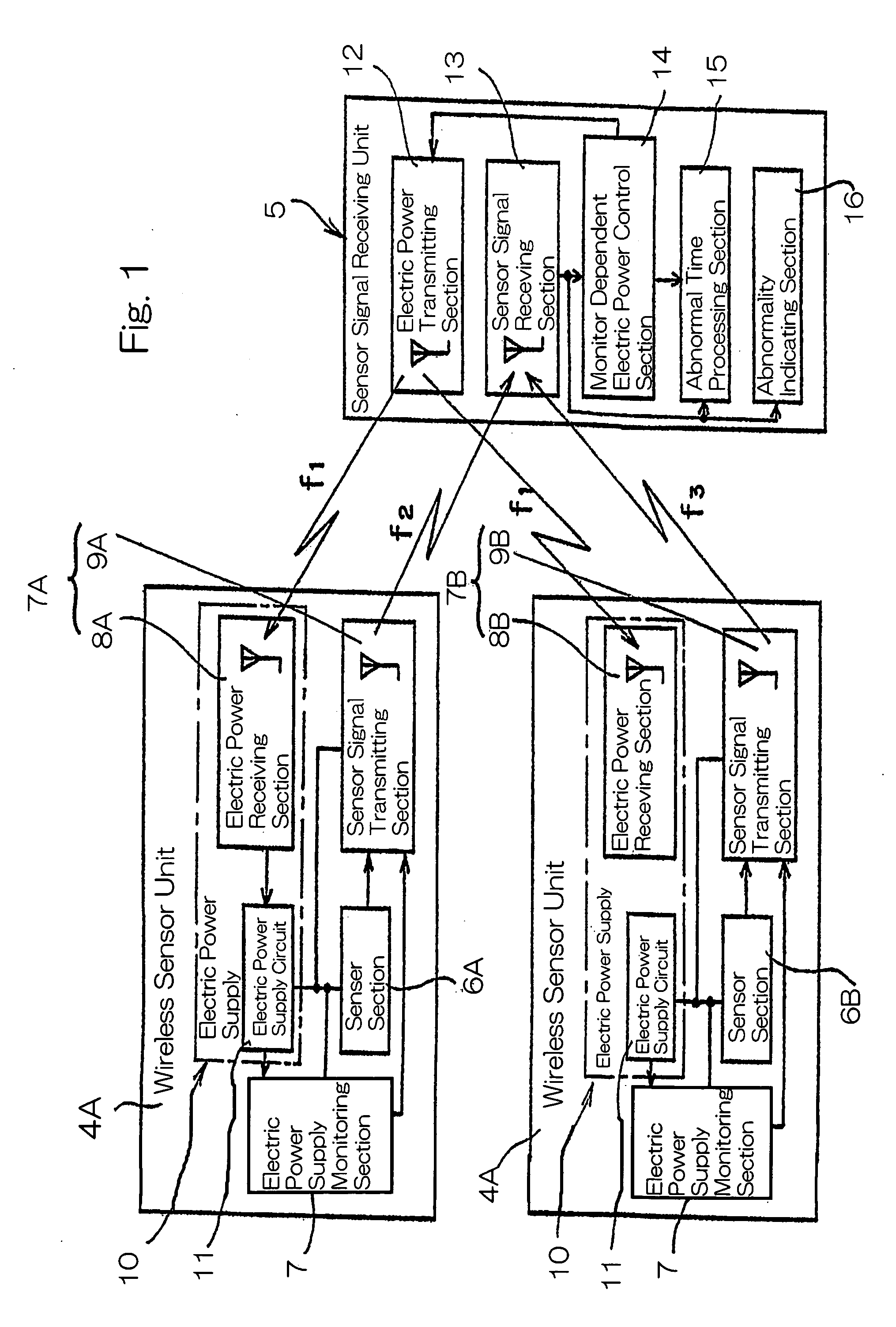
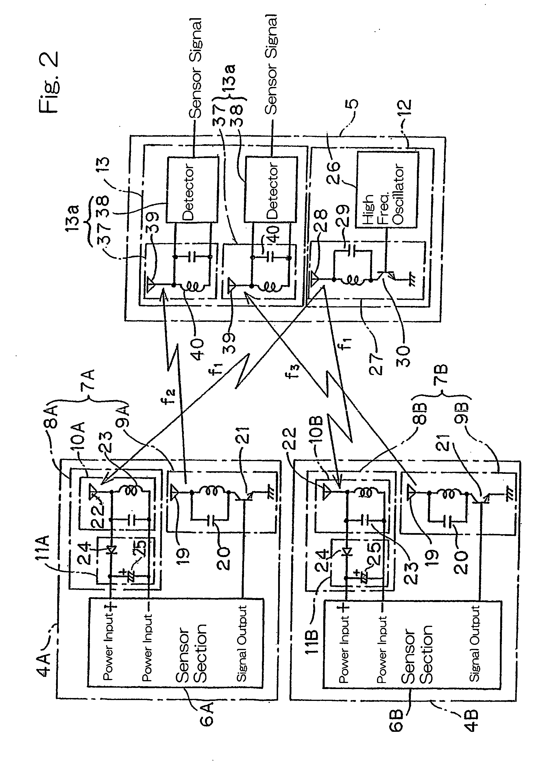
[0041] A wireless sensor system according to a first preferred embodiment of the present invention will be described with particular reference to FIG. 1. This wireless sensor system includes a plurality of wireless sensor unit 4A and 4B, and a sensor signal receiving unit 5 for supplying by wireless an electric power to each of those wireless sensor units 4A and 4B and also for receiving by wireless sensor signals from the respective wireless sensor units 4A and 4B. The number of the wireless sensor units employed is not specifically limited to a particular number and one or more than two wireless sensor units may be employed, it being however to be noted that the use of the two wireless sensor units is shown in FIG. 1.

[0042] Each of the wireless sensor units 4A and 4B includes a sensor section 6A or 6B and a transmitting and receiving section 7A or 7B. Each of the sensor sections 6A and 6B defines means for detecting an object to be detected or detection object and at least one of...


PUM


Abstract

To provide a wireless sensor system, in which an abnormal power supply in the power supply section can be ascertained, for avoiding a malfunction of the system and accomplishing a stable power supply with reduction of the consumption of a power being transmitted, the wireless sensor system includes wireless sensor units and a sensor signal receiving unit. The wireless sensor units include a sensor section for detecting a detection object, a sensor signal transmitting section for transmitting by wireless a sensor signal from the sensor section, and a power supply section having a power receiving section for receiving a driving power transmitted by wireless. In this system, a power supply monitoring section is provided for monitoring the voltage of the power supply section. The sensor signal receiving unit includes a monitor dependent power control section for regulating the power to be transmitted, depending on a monitored result of the power monitoring section.

Description

FIELD OF THE INVENTION [0001] The present invention relates to a wireless sensor system for wirelessly transmitting various sensor signals, for example, those generated from various sensors installed in a wheel support bearing assembly in various machine, equipment and automotive vehicles and also to a wheel support bearing assembly utilizing such wireless sensor system. BACKGROUND ART [0002] A wireless ABS (anti-skid brake system) sensor system has been suggested, in which sensor signals generated from a revolution sensor mounted on a wheel support bearing assembly is transmitted by wireless between a vehicle wheel and an automotive body to thereby eliminate the use of harnesses. On the other hand, the Japanese Laid-open Patent Publication No. 2003-146196, published May 21, 2003, discloses the system in which in a wheel support bearing assembly equipped with a revolution sensor, output signals of which are transmitted by wireless, the presence or absence of an abnormality in the re...

Claims


Application Information

Patent Timeline
IPC IPC(8): G08B21/00G01P3/44G08C17/00
CPCF16C41/004F16C41/008G08C17/00G01P3/443F16C19/06F16C19/186F16C19/187F16C19/386
Inventor MIZUTANI, MASATOSHIITO, HIROYOSHISAHASHI, KOJIOKADA, KOICHI
Owner NTN CORP
Why Eureka
Try Eureka