Planar inverted F antenna and method of making the same

a technology of inverted antennas and antennas, applied in the direction of radiating element structural forms, elongated active element feeds, resonance antennas, etc., can solve the problems of antennas that go against industrialization manufacture, mobile phone antennas working in gsm mostly cannot be set in notebooks or other portable wireless communication devices, etc., to achieve the effect of reducing size and simplifying structur

Inactive Publication Date: 2007-01-25
HON HAI PRECISION IND CO LTD
View PDF6 Cites 29 Cited by
  • Summary
  • Abstract
  • Description
  • Claims
  • Application Information

AI Technical Summary

Benefits of technology

[0008] A primary object, therefore, of the present invention is to provide a planar inverted-F antenna with simplified structure and reduced size.

Problems solved by technology

However, user would not satisfy a portable wireless communication devices only working in WLAN in the future.
However, antennas of the mobile phone working in GSM mostly cannot be set in notebook or other portable wireless communication device because of size or power.
Complex configuration and taking up more space result in the antenna going against industrialization manufacture, wasting cost and breaching trend of miniaturization development of antenna.

Method used


Image

  • Planar inverted F antenna and method of making the same
  • Planar inverted F antenna and method of making the same
  • Planar inverted F antenna and method of making the same

Examples


Embodiment Construction

[0018] Reference will now be made in detail to a preferred embodiment of the present invention.

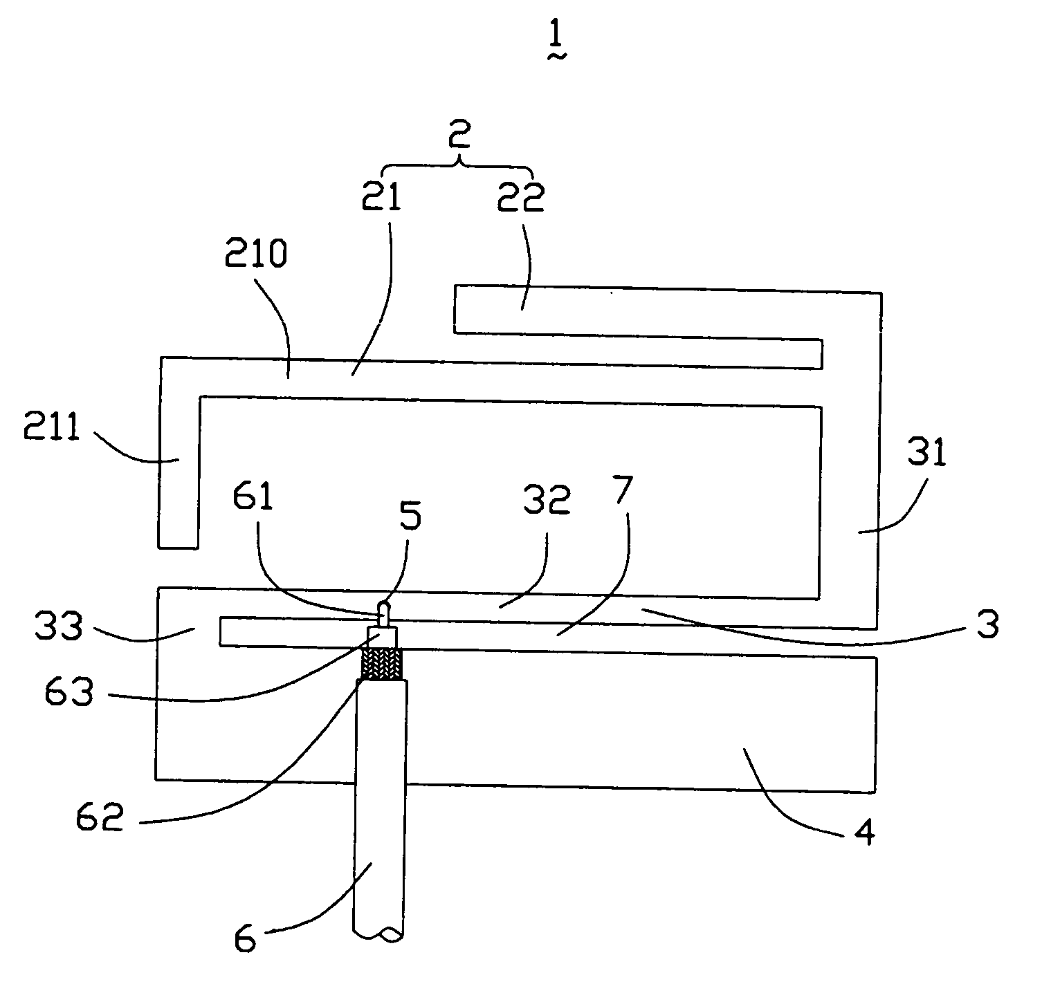
[0019] Referring to FIG. 1, a planar inverted-F antenna 1 according to the present invention is made of a metal sheet and comprises a radiating portion 2, a grounding portion 4, and a connecting portion 3 connecting the radiating portion 2 and the grounding portion 4.

[0020] The radiating portion 2 comprises a first radiating element 21 operating at a lower frequency and a second radiating element 22 operating at a higher frequency and extending along a first direction. The first radiating element 21 is of L-shape and comprises a first part 210 extending along the first direction and parallel to the second radiating portion 22 and a second part 211 extending along a second direction from left end of the first part 210 toward the grounding portion 4. The L-shape design of the first radiating element 21 is capable of avoiding adding the lateral size of the planar inverted-F antenna 1. The c...


PUM


Abstract

A multi-band antenna (1) used in wireless communications includes a radiating portion (2), a grounding portion (4), and a connecting portion (3). The radiating portion (2) includes a first radiating element (21) operating at 900 MHz frequency band and a second radiating element (22) operating at 1800 MHz frequency band. The connecting portion (3) connects the radiating portion (2) and the grounding portion (4). The grounding portion (4), the radiating portion (2), and the connecting portion (3) locate in the same plane.

Description

BACKGROUND OF THE INVENTION [0001] 1. Field of the Invention [0002] The present invention relates generally to an antenna, and more particularly to a planar inverted-F antenna (PIFA) used in a portable electronic device. [0003] 2. Description of the Prior Art [0004] With the development of wireless communication, more and more portable electronic devices, for example note book, install an antenna system for working in a Wireless Local-area Network (WLAN). Transmitting and receiving signals plays an important role in wireless communication process. In recent years, a majority of WLAN bases on Bluetooth technical standard or 802.11 technical standard. Antenna in Bluetooth technical standard bases on 2.4 GHz frequency band, and in 802.11 technical standard bases on 2.4 GHz and 5 GHz. So, antenna in notebook mostly works in the above frequency bands at the present time. [0005] However, user would not satisfy a portable wireless communication devices only working in WLAN in the future. I...

Claims


Application Information

Patent Timeline
Patent Type & Authority Applications(United States)
IPC IPC(8): H01Q1/38
CPCH01Q1/2216H01Q1/243H01Q5/371H01Q9/42H01Q9/0421
Inventor KU, PO-KANGTAI, LUNG-SHENGHUNG, CHEN-TAKE, YUN-LONGHUANG, YAO-SHIEN
Owner HON HAI PRECISION IND CO LTD
Why Eureka
Try Eureka