Stereoscopic picture display device and method of producing the same

a stereoscopic image and display device technology, applied in the field of stereoscopic image display devices, can solve the problems of thermal expansion of the gap between the liquid crystal display panel and the liquid crystal parallax barrier must be bigger, and the display quality of the stereoscopic image display device is worsened

Active Publication Date: 2007-01-25
138 EAST LCD ADVANCEMENTS LTD
View PDF6 Cites 15 Cited by
  • Summary
  • Abstract
  • Description
  • Claims
  • Application Information

AI Technical Summary

Benefits of technology

[0024] Further, producing the stereoscopic image display device through this manufacturing method is easier compared to the conventional operation of adhering by the use of double-sided adhesive tape because only one coating of adhesive agent is required, and bubbles do not occur, yet the parts are more firmly fixed. Further, the region formed by the spacer me...

Problems solved by technology

However, the gap between the liquid crystal display panel and the liquid crystal parallax barrier must be bigger as mentioned above as the stereoscopic image display device becomes larger.
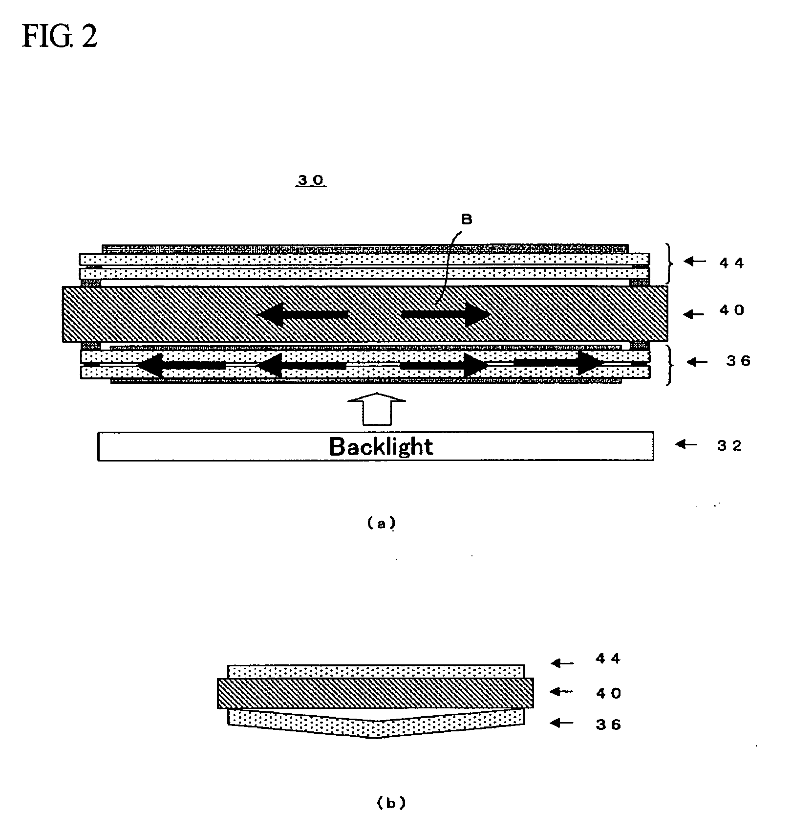
Further, heat generated by the backlight used in the stereoscopic image display device causes thermal expansion of the liquid crystal parallax barrier, the spacer member, and the glass substrate used in the liquid crystal display panel.
Furthermore, since the distance from the backlight is different for each glass substrate, the glass substrates are consequently bent due to varying thermal expansion rates, and because the stereoscopic image display device is formed by stacking the liquid crystal ...

Method used


Image

  • Stereoscopic picture display device and method of producing the same
  • Stereoscopic picture display device and method of producing the same
  • Stereoscopic picture display device and method of producing the same

Examples


Embodiment Construction

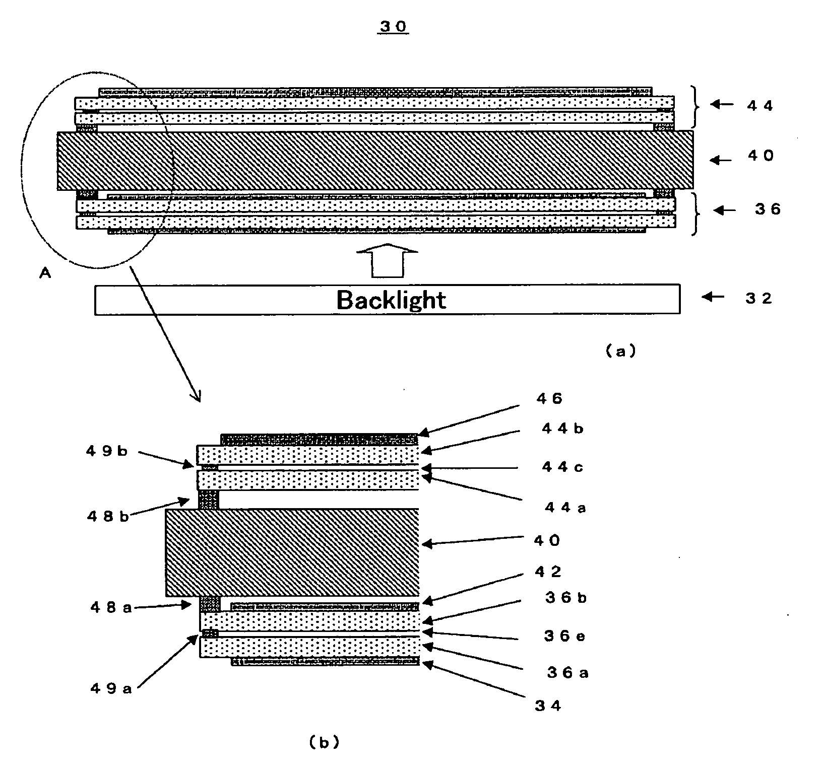
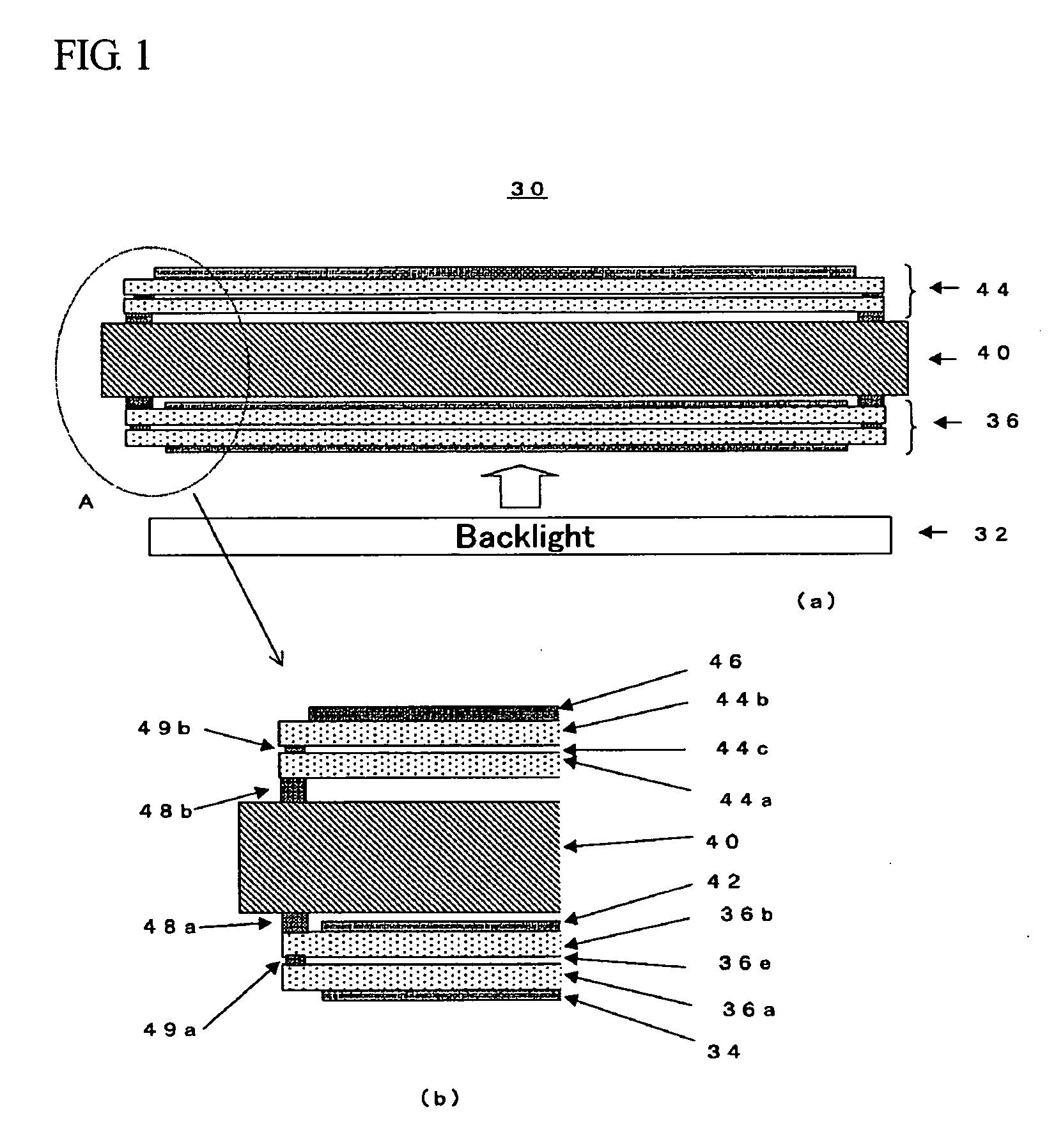
[0030] In the following, embodiments of the stereoscopic image display device according to the present invention will be described with reference to the attached drawings. FIG. 1 is the view showing the constitution of a stereoscopic image display device 30 according to the present invention, where FIG. 1(a) is a schematic cross-sectional view thereof and FIG. 1(b) is the enlarged view of the portion marked A of FIG. 1. The stereoscopic image display device 30 according to the present invention is constituted by arranging a liquid crystal display panel 36 and a liquid crystal parallax barrier 44, adhered together by an adhesive agent while sandwiching a spacer member 40 such as a glass substrate, above a backlight 32.

[0031] The liquid crystal display panel 36 is a transmissive liquid crystal panel consisting of a rear glass plate 36a located on the incident side of light, a front glass plate 36b located on the output side of light, pixel electrodes (not shown) formed on the inner s...


PUM


Abstract

A stereoscopic image display device 30 comprising a backlight 32, a liquid crystal display panel 36, a liquid crystal parallax barrier 44, and a spacer member 40 arranged between the liquid crystal display panel 36 and the liquid crystal parallax barrier 44, in which the spacer member 40 is made of a glass material different from that of the glass substrates 36a, 36b constituting the liquid crystal display panel 36, and the spacer member 40 is a glass substrate having a thermal expansion coefficient larger than that of the glass substrates 36a, 36b constituting the liquid crystal display panel 36. More specifically, it is preferable that the spacer member 40 consist of a soda glass substrate and that the liquid crystal display panel 36 for display be formed of non-alkali glass. With this constitution, it is possible to provide a stereoscopic image display device, which can be used as a large-sized stereoscopic image display device by means of the liquid crystal parallax barrier method, with good display quality and where due consideration has been given to the thermal expansion of the substrate caused by heat generated by the backlight, and the manufacturing method therefor.

Description

TECHNICAL FIELD [0001] The present invention relates to a stereoscopic image (picture) display device based on a liquid crystal parallax barrier system, which is capable of stereoscopic image display without using special glass and more specifically, to a stereoscopic image display device where consideration is given to the thermal expansion of the substrate caused by heat generated by a backlight, and the method of manufacturing the device. BACKGROUND ART [0002] The known conventional methods of displaying stereoscopic images without using special glass are the lenticular method, the parallax barrier method, and a method in which a light source is formed in the shape of slits. [0003]FIG. 4 is a schematic view showing the principle of stereoscopic image display based on the parallax barrier method. Images that an observer ca view are formed on a liquid crystal display panel 50. To realize stereoscopic vision, left-eye-pixels L for displaying images for the left eye and right-eye-pix...

Claims


Application Information

Patent Timeline
IPC IPC(8): G02F1/1335G02B30/31G02F1/1347
CPCG02F1/1347G02B27/2214G02B30/31G02F1/1335G02B30/27
Inventor TANAKA, SHINICHIROARAMATSU, YOSHIAKI
Owner 138 EAST LCD ADVANCEMENTS LTD
Why Eureka
Try Eureka