Projector device

Active Publication Date: 2007-01-25
SANYO ELECTRIC CO LTD
View PDF14 Cites 31 Cited by
  • Summary
  • Abstract
  • Description
  • Claims
  • Application Information

AI Technical Summary

Benefits of technology

[0018] Therefore, according to the above specific configuration, the exhaust temperature can be lowered while minimizing enlargement of the device due to an increased mounting space for the exhaust system.
[0019] Specifically, the first exhaust fan and the second exhaust fan are each attached with an inclination angle relative to the wall surface of the casing. If one of the first and second exhaust fans is placed parallel with the wall surface of the casing, for example, the other fan must be placed greatly inclinedly relative to the wall surface of the casing, requiring a large space for mounting the exhaust system. In contrast, with the above specific configuration, the first exhaust fan and the second exhaust fan have the same or approximately same inclination angle relative to the wall surface of the casing, thereby keeping the necessary space for mounting the exhaust system

Problems solved by technology

However, because the exhaust system is usually placed with an inlet direction thereof toward the lamp with a great heat amount, the exhaust system discharges high te

Method used


Image

  • Projector device
  • Projector device
  • Projector device

Examples


Embodiment Construction

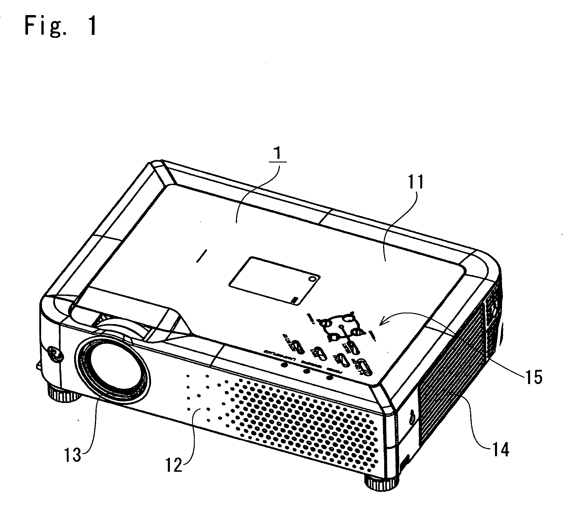
[0049] The present invention embodied in a liquid crystal projector device will be specifically described below with reference to the drawings. In the description given below, the image projection direction of the liquid crystal projector device shown in FIG. 1 is defined as the forward direction, and right and left are defined by facing the front face of the liquid crystal projector device.

Overall Construction

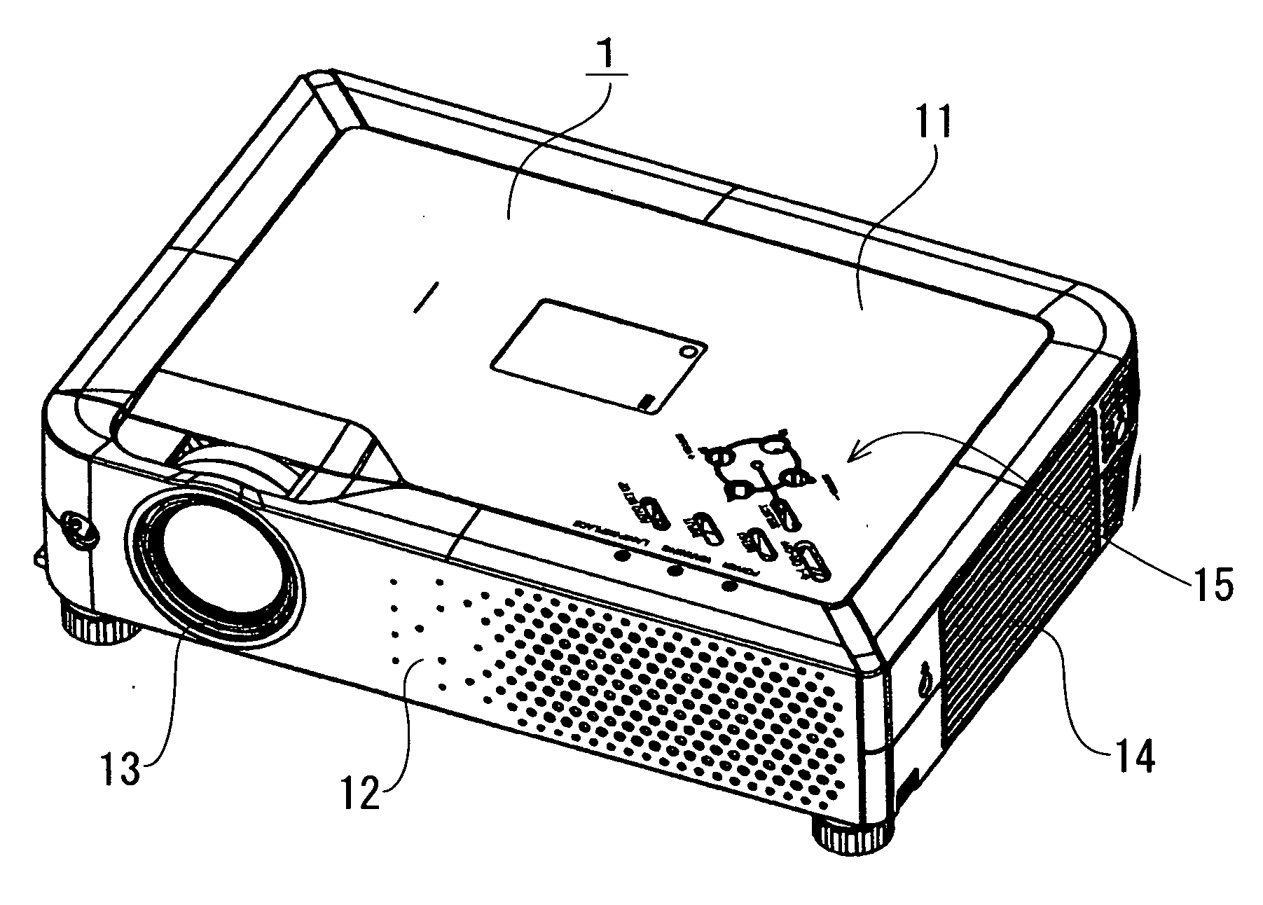
[0050] As shown in FIG. 1, the liquid crystal projector device of the present invention includes a flat casing 1 including a lower half case 12 and an upper half case 11. A manipulation portion 15 including a plurality of manipulation buttons is disposed on a surface of the casing 1, while a projection window 13 is provided on the front face of the casing 1. A vent 14 for discharging the air in the casing 1 to the outside is provided on the right side wall of the casing 1.

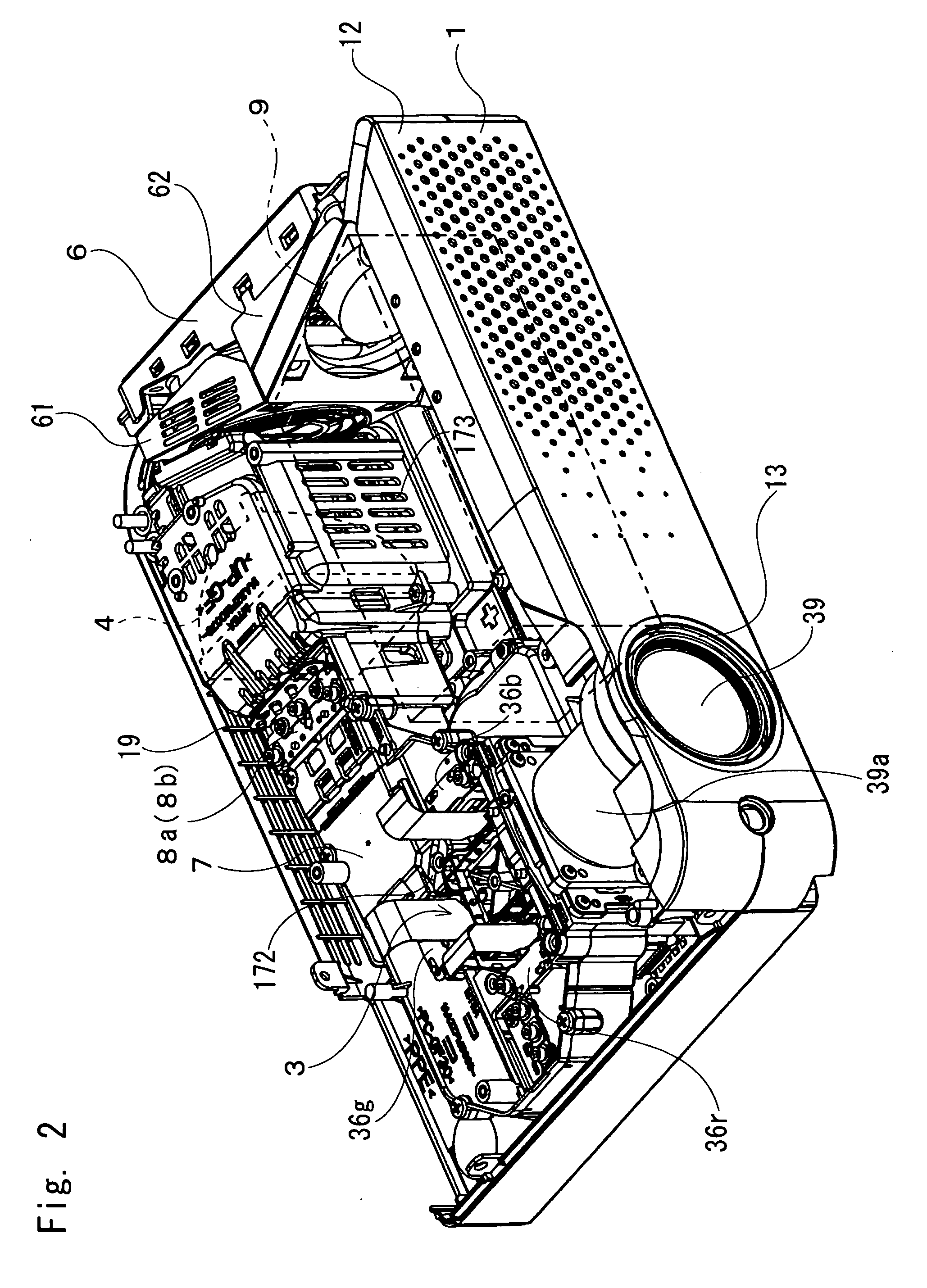
[0051] As shown in FIG. 2 and FIG. 3, a synthetic resin optical system holding case 7 extending in an ...


PUM


Abstract

A liquid crystal projector device of the present invention includes a casing having disposed therein a lamp unit, an optical system for receiving light from the lamp unit to generate image light, and a power unit. An exhaust system for cooling an inside of the casing is attached to a side surface of the casing. The exhaust system includes a first exhaust fan and a second exhaust fan, which stand along the side surface of the casing. The first exhaust fan is placed toward the lamp unit, while the second exhaust fan is placed toward the power unit. Exhaust directions of both exhaust fans intersect each other.

Description

[0001] The priority application Number 2005-209288 upon which this patent application is based is hereby incorporated by reference. BACKGROUND OF THE INVENTION [0002] 1. Field of the Invention [0003] The present invention relates to a projector device adapted to guide light from a light source to an optical system to generate image light for magnification projection on a forward screen. [0004] 2. Description of Related Art [0005] A conventional projector device of this type includes a casing having disposed therein a lamp for serving as a light source, and an optical system including a polarization beam splitter, a polarizing plate, liquid crystal panels, a projection lens, etc. An exhaust system is arranged along a wall surface in the casing. The exhaust system causes air inside the casing to flow to thereby prevent temperature rise inside the casing (see JP 8-275096, A). [0006] However, because the exhaust system is usually placed with an inlet direction thereof toward the lamp wi...

Claims


Application Information

Patent Timeline
IPC IPC(8): G03B21/18
CPCG03B21/18
Inventor NAKAGAWA, NORIOSARUWATARI, TOSHIHIRO
Owner SANYO ELECTRIC CO LTD
Why Eureka
Try Eureka