Exhaust gas cleaning system

a technology of exhaust gas and purification system, which is applied in the direction of mechanical equipment, machines/engines, electric control, etc., can solve the problems of deteriorating fuel efficiency, difficult control during regeneration, and simple engine improvements in response to such intensified regulations are not sufficient to realize full compliance, so as to improve the ignition performance and combustion performance of injected fuel, and avoid torque fluctuation. , the effect of improving fuel efficiency

Active Publication Date: 2006-09-14
ISUZU MOTORS LTD
View PDF6 Cites 21 Cited by
  • Summary
  • Abstract
  • Description
  • Claims
  • Application Information

AI Technical Summary

Benefits of technology

[0033] The above-described filter is formed from a filter with oxidation catalyst, PM oxidation catalyst, or the combination thereof. As a result of this configuration, the exhaust temperature to start combustion of particulate matters accumulated in the filter can be lowered, compared to when the filter does not support catalyst. Accordingly, fuel efficiency can be improved.
[0034] Using the exhaust gas purifying system according to the present invention, it is possible to perform PM combustion for efficient PM regeneration even in an idling or low-load driving condition, in which forced combustion of the PM accumulation in the filter was impossible, in case of the prior art, because of a low exhaust temperature. In other words, delay multi-step injection performed in combination with exhaust throttling and exhaust temperature regulation through adjustment of the degree of opening of the exhaust throttling improve the ignition performance as well as the combustion performance of the injected fuel. Consequently, while avoiding the occurrence of torque fluctuation and the extreme generation of white smoke, temperature raising control of the exhaust gas is carried out with acute sensitivity, not only to changes in the exhaust temperature on the upstream side of the oxidation catalyst, but also to changes in the exhaust temperature on the downstream thereof. Accordingly, even when the fuel required for raising the temperature of the exhaust gas is in short supply, it is possible to significantly increase the temperature of the exhaust gas in an efficient manner. As a result, PM combustion for efficiently regenerating PM can be carried out.
[0035] Accordingly, this exhaust gas purifying system provides a continuous regeneration DPF capable of preventing the occurrence of white smoke and capable of reducing torque fluctuation during regeneration control for DPF regeneration.

Problems solved by technology

Simple engine improvements in response to such intensification of regulations are not sufficient to realize full compliance.
And accordingly, problems such as deteriorated fuel efficiency, difficulty in maintaining control during regeneration, and the need for a double DPF system performing alternate PM accumulation and PM combustion (or DPF regeneration) are experienced.
This in turn leads to the problem of the need for increasingly large and complex systems.
Consequently, in case that the engine remains in a state of idling, low-load driving, or the like, conditions for initiating PM oxidation are not achieved, even if PM accumulates.
Therefore, exhaust pressure rises, and fuel efficiency is deteriorated as a result.
Furthermore, there is a danger of engine stopping and other similar problems.
Specifically, this comprises multi-step injection of small injection quantity prior to main injection and significant delay of main injection.
This dual process raises the engine's exhaust pressure, increases the amount of residual exhaust gas in the intake process, and in addition, raises the temperature of the exhaust gas.
However, in the control of DPF regeneration characteristic of the prior art, in which multi-step injection is used in combination with this exhaust throttling, when controlled driving is carried out for the purpose of regeneration, there is a problem of excessively large torque fluctuation.
Furthermore, this control is also problematic in that white smoke is emitted.
Accordingly, when normal injection control is restored, torque fluctuation occurs as a result of sudden changes in exhaust pressure and large changes in injection timing.
However, torque fluctuation occurs in such cases as well.
Furthermore, when switching from multi-step injection in combination with exhaust throttling to normal injection control, the corresponding changes in injection quantity can lead to the generation of HC and white smoke.

Method used


Image

  • Exhaust gas cleaning system
  • Exhaust gas cleaning system
  • Exhaust gas cleaning system

Examples


Embodiment Construction

[0046] Hereinafter, the preferred embodiments of the exhaust gas purifying system according to the present invention will be described with reference to the accompanying drawings. The following explanation will use the example of an exhaust gas purifying system provided with a continuous regeneration diesel particulate filter (DPF) comprising a combination of an oxidization catalyst (DOC) and a filter with a catalyst (CSF).

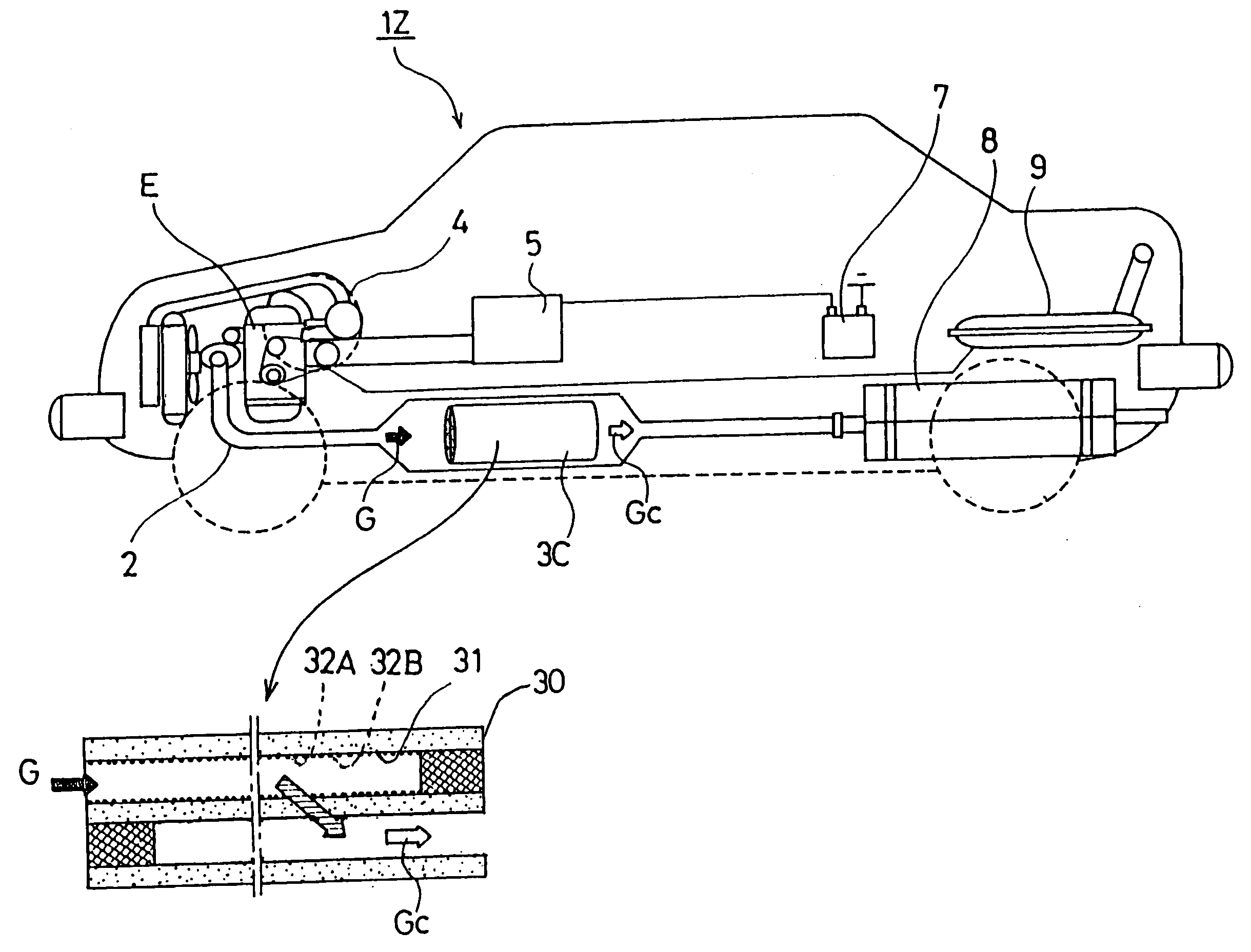
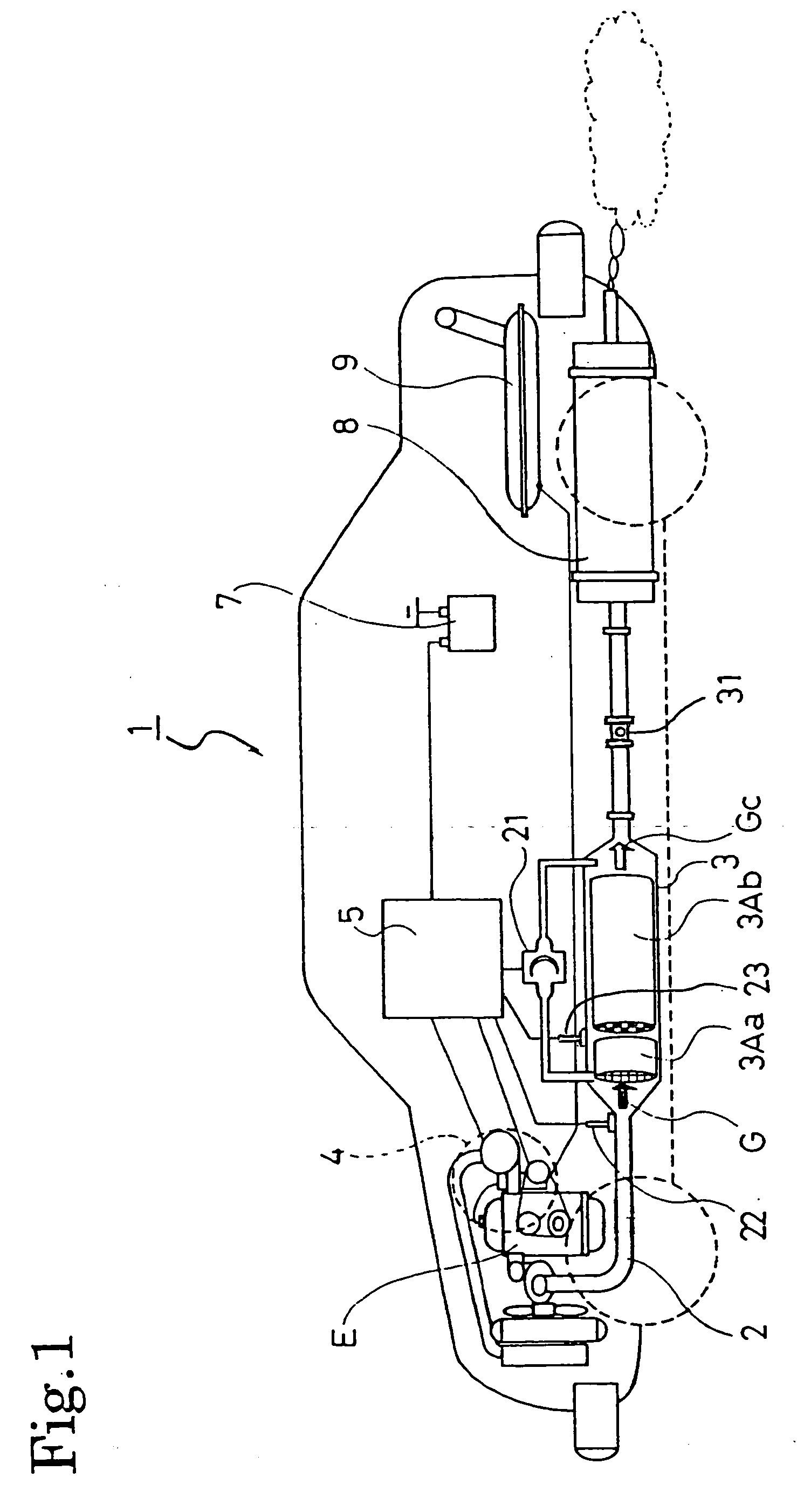
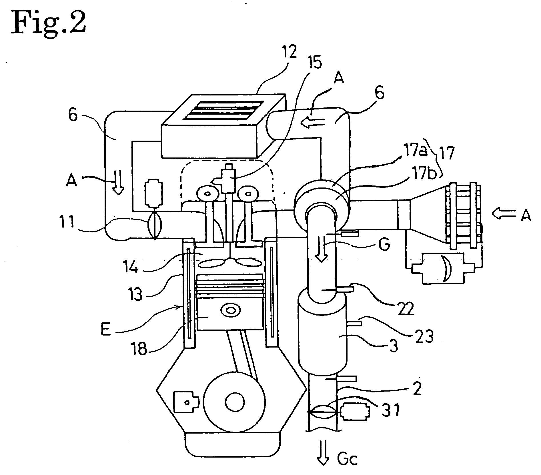
[0047]FIG. 1 and FIG. 2 show the configuration of an exhaust gas purifying system 1 according to an embodiment of the present invention. In this exhaust gas purifying system 1, a continuous regeneration DPF 3 is provided in the exhaust passage 2 connected to the exhaust manifold of a diesel engine E. This continuous regeneration DPF 3 has an oxidation catalyst 3Aa on the upstream side thereof and a filter 3Ab with a catalyst on the downstream side thereof.

[0048] The oxidation catalyst 3Aa is formed so as to carry an oxidization catalyst of platinum (Pt) and the ...


PUM


Abstract

An exhaust gas purifying system causes less torque fluctuation and is capable of preventing the occurrence of white smoke in a regeneration control operation for regenerating a continuous regeneration DPF 3. When the continuous regeneration DPF 3 with an oxidation catalyst 3Aa on the upstream side of a filter 3Ab is controlled to regenerate, an exhaust throttle valve 31 provided in an exhaust passage 2 is closed and a delay multi-step injection control is performed to increase the temperature of the exhaust gas if an exhaust temperature T1 at the inlet of the oxidation catalyst 3Aa is less than the activation temperature Ta of the oxidation catalyst. After the exhaust temperature T1 at the inlet of the oxidation catalyst 3Aa has risen to the activation temperature Ta of the oxidation catalyst or higher, the exhaust throttle valve 31 is opened in a stepwise or continuous manner so that the exhaust temperature T2 at the inlet of the filter 3Ab rises to a lower limit temperature of PM forced combustion Tb1 or higher.

Description

TECHNICAL FIELD [0001] The present invention relates to an exhaust gas purifying system with a continuous regeneration diesel particulate filter that purifies exhaust gas discharged from an engine. BACKGROUND ART [0002] In the same way as for NOx, CO, and also HC etc., restrictions on the volume of Particulate Matter (hereinafter referred to as “PM”) discharged from diesel engines grow stricter every year. Simple engine improvements in response to such intensification of regulations are not sufficient to realize full compliance. Techniques for accumulating the PM discharged from engines in a filter known as a Diesel Particulate Filter (hereinafter referred to as “DPF”) and for reducing the volume thereof through being externally discharged are also being developed. [0003] Ceramic monolithic-honeycomb wall-flow type filters, mesh-type filters using ceramic or metallic fibers, and the like are available as such DPFs for direct accumulation of PM. In the same way as other exhaust gas p...

Claims


Application Information

Patent Timeline
Patent Type & Authority Applications(United States)
IPC IPC(8): F01N3/10F01N3/02F01N3/023F01N3/20F01N3/24F01N3/28F01N11/00F01N13/08F02B37/00F02D41/02F02D41/04F02D41/38F02D41/40F02D45/00
CPCF01N3/0231F01N3/0235F01N9/002F01N2250/02F01N2430/08F01N2430/085F01N2510/065F02B37/00F02D41/029F02D41/401F02D41/402F02D41/403F02D2200/0802Y02T10/44Y02T10/144Y02T10/47F01N13/0097Y02T10/12Y02T10/40
Inventor GABE, MASASHITASHIRO, YOSHIHISA
Owner ISUZU MOTORS LTD
Why Eureka
Try Eureka